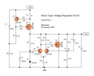
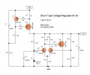
Babowana said:R6, Z1 and C2 are providing a voltage reference where R6 decides the size of zener current while C2 is reducing zener noise and ripple and acting for a gentle start.
Maybe I'm talking too much in the first morning of Happy Lunar New Year . . .
Do you have any advice or comment on this? Too old fashioned style?
Cheers,
>>🙂<<
Tie R6 under the CCS Mosfet (Q2) instead of Vin. Also consider an individual CCS, maybe an IDSS connected JFET instead of R6. The way you have it now its referring to a ripple ridden line without current stabilization. It will work but not in best performance.
Good luck.
connect R6 where +18 rail is - cleaner supply
split same R6 in two halves , connect their junction with 220n to gnd
decrease C2 a much you can - 2u2 is good enough
put 100n from pot wiper to + rail
split same R6 in two halves , connect their junction with 220n to gnd
decrease C2 a much you can - 2u2 is good enough
put 100n from pot wiper to + rail
Thanks, Salas and ZenMod, for your advices.
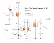
I have reconnected R6 to the regulated voltage rail. I however would like to keep R6 without replacing it with the Jfet CCS because I want to have the "gentle start" which is possible by a proper RC combination. For the same reason, I'd like to keep the C2 size as big. And, the bigger size C2 would be efficient in lowering the critical frequency of the RC circuit, and so to be the cap of a good ac short.
C4 is added to the wiper of P1 from the regulated voltage rail.
Here is the revision . . .
>>🙂<<
Attachments
Hi,
I see your introduction talks about a 60mA to 70mA CCS.
Are you thinking about this design with a capability to around 1A?
The FETs are far too expensive and big and slow due to the capacitance for your <100mA duty.
If the output is shorted and you have 30Vdc+10% on the input, Q2 peak dissipation is only 2.1W A 5W to 10W device with a clip on heatsink will do this duty. Normally it dissipates only 1W.
If the output is open circuit the Q4 maximum dissipation is 1W. Again a 5W to 10W device is sufficient.
Go back and read Zen Mod again. You ignored most of his advice.
I understand the slow start requirement. Do that with the split R6 & cap.
What voltage is 1n4739? I would use a 9 or 10V Zener here, about half the output voltage.
Try to adjust R6 to get >=10% dissipation in this Zener.
Check the Vgs of the two FETs and see whether your component values allow these voltages to exist.
Babo, if you insist on R6, at least decrease it's value to 1K5 - 1K8. That way the zener diode won't be generating much noise (which it does when underbiased)
🙂
🙂
18V across 1k8 + 9.1V Zener gives ~5mA current and ~11% dissipation for a 400mW Zener. Pretty close to >=10%.juma said:Babo, if you insist on R6, at least decrease it's value to 1K5 - 1K8. That way the zener diode won't be generating much noise (which it does when underbiased)
🙂
Hei,
I don't want to insist anything 😉 I want to discuss about preferance and why.
When I moved R6 connection from +30V down to +18V rail, I didn't do re-calculation of zener current to adjust R6 size. According to datasheet, 1N4739 (9V1) has an ideal breakdown voltage curve, i.e. almost 9.1V even at very low current through the zener. Even if I can't get 9.1V, it would be okay because P1 makes me possible to lift up the regulated rail voltage to the level I want. Actually, P1 was there to allow flexibility of the reference voltage and the regulated rail voltage.
Anyhow . . .
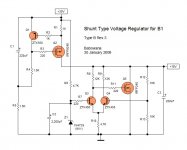
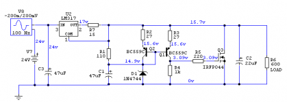
I changed R6 size down to 1.5K here in this revision 2 for me to be sure of the 9V1 zener current. And, I removed P1 and C4 leaving R12 and R13. No more such luxurious flexibility. 9V1 reference voltage and +18V rail voltage, that's all 🙂
I still didn't slit R6 in two to insert a capacitor. If I do, it could make a good RC filter to better clean up noise. But, I think that the big sized C2 would do this job very well . . .
In addition, I changed values of R2, R4 and R5
>>🙂<<
I don't want to insist anything 😉 I want to discuss about preferance and why.
When I moved R6 connection from +30V down to +18V rail, I didn't do re-calculation of zener current to adjust R6 size. According to datasheet, 1N4739 (9V1) has an ideal breakdown voltage curve, i.e. almost 9.1V even at very low current through the zener. Even if I can't get 9.1V, it would be okay because P1 makes me possible to lift up the regulated rail voltage to the level I want. Actually, P1 was there to allow flexibility of the reference voltage and the regulated rail voltage.
Anyhow . . .
I changed R6 size down to 1.5K here in this revision 2 for me to be sure of the 9V1 zener current. And, I removed P1 and C4 leaving R12 and R13. No more such luxurious flexibility. 9V1 reference voltage and +18V rail voltage, that's all 🙂
I still didn't slit R6 in two to insert a capacitor. If I do, it could make a good RC filter to better clean up noise. But, I think that the big sized C2 would do this job very well . . .
In addition, I changed values of R2, R4 and R5
>>🙂<<
Attachments
Babowana said:Anyhow . . .
Babo, bad news. It does not work in my simulation. Gives 4.9V out.
I hope I did it wrong somewhere.
Attachments

Oh . . .
I have just watched Monk (Adrian) and Cold Montain on TV . . .
It's already a deep and cold night . . .
Bad news
but thanks, Salas.
Could you kindly try your simulation with the attached here?
I would much appreciate it.
I will come back later as I should go to bed now . . . tired . . .
Cheers,
>>🙂<<
Attachments
has anybody bothered to ask the simulators what the Vgs of each FET is yet?
What about asking what currents are flowing in the collector resistors of the LTP?
I would learn far more by doing a manual calculation than worrying about whether a simulator says it works or not. Maybe you can too.
Once you have the component values in the right range to get the circuit working then start investigating the finer details on the simulator.
Babowana said:Oh . . .
I have just watched Monk (Adrian) and Cold Montain on TV . . .
It's already a deep and cold night . . .
Bad news
but thanks, Salas.
Could you kindly try your simulation with the attached here?
I would much appreciate it.
I will come back later as I should go to bed now . . . tired . . .
Cheers,
>>🙂<<
Babo - click on my sig , and download Cook Book ;
look what values of resistors are in Shunty's differential stage
Babowana said:Could you kindly try your simulation with the attached here?
I would much appreciate it.>>🙂<<
I did, and unfortunately, does even worse.
Attachments
AndrewT said:has anybody bothered to ask the simulators what the Vgs of each FET is yet?
What about asking what currents are flowing in the collector resistors of the LTP?
I would learn far more by doing a manual calculation than worrying about whether a simulator says it works or not. Maybe you can too.
Once you have the component values in the right range to get the circuit working then start investigating the finer details on the simulator.
It won't work if it does not work on the simulator. I have made many shunts with this procedure, and the real circuit was always measuring spot on prediction.
Hi, Salas
Thank you very much for the help.
I trust your simulation. So, I'd like to figure out why the attached circuit is not working. By the way, the quality of my head is getting worse. Even if the quality is still acceptable, the efficient working time is limited, e.g. 2-3 hours per day. I think this is due to my current weak body condition supporting the mental activities . . . It would take time for me alone find out the problem. I need your (all of you) kind help 🙂
I will come back this weekend . . . I'm going to simulate my body condition, 😀 . . .
>>🙂<<
Attachments
Mpravo file mou - einai omorfia auto to kukloma, sugxaristiria !
I tried a quick mock-up of your shunt (point-to-point) and it works like a charm. Input was from wall-wart with very high ripple (200 mV peak) and instead of your discrete CCS I used LM317 as CCS set for 85 mA. I loaded the shunt with 10mA to 60 mA and there was no sign of ripple or oscillation on my scope (10mV/DIV sensitivity). I used the parts that I had at hand and it worked nicely from the start.
Test with JFET BOZ (circuit with no PSR at all) was successful - no hum, no hiss, completely black background, sounds lovely, noticeably better than 7815.
Good job, thank you ! 🙂
Attachments
In case I missed it along the way, what is the hypothesis as to
why shunt regulators are superior?
😎
why shunt regulators are superior?
😎
juma said:Mpravo file mou - einai omorfia auto to kukloma, sugxaristiria !
Good job, thank you ! 🙂
For the international reader, what juma wrote in Greek is: ''Bravo my friend - this circuit is a beauty, congratulations !''
Thanks juma, it will do better in the highs when you find the opportunity to substitute the LM317 with the IRFP I proposed. Babo will be pleased to hear, will give him strength.
Nelson Pass said:In case I missed it along the way, what is the hypothesis as to
why shunt regulators are superior?
😎
No hypothesis from my side Nelson, no ABX subjective tests, no real engineering skills. Just thinking and testing simple ideas in good will and confidence. Surprisingly, I get top feedback from around the globe for those low and high voltage simplistic shunts. I always work the soldering iron and evaluate carefully with the help and cross evaluation of energetic DIY friends before I recommend something, that's all. If you have some ideas of whys and whats for shunts - you are the main man around - please tell.

- Status
- Not open for further replies.
- Home
- Amplifiers
- Pass Labs
- New-building of my B1 buffer