Note that I was referring to the classic single-stage" CFA" and not Dadod's offering.I am simply claiming that to mitigate the gain droop apparent in a bipolar OPS, you can use an EF3. We can get into a circular semantic exchange but that of course leads to nowhere.
"Notwithstanding Dadod's two-stage offering, I still maintain that the standard "CFA" is useless as a linear audio frequency amplifier principally because its forward-path gain is only that of a single common-emitter stage. This means that this topology does not generate anywhere near enough loop gain to mitigate its own non-linearity, never mind that of the output stage to which it is attached."
Its difficult to take statements like this seriously. (Dadod's is not the only high loop gain CFA out their BTW)
🙂
You can still raise the CFA loop gain by increasing the front end gm. This will require matching the Vbe and hFE of the DB transistors - this more in line with the IC approach.
I agree that the loop gains are in general much lower than VFA in simple classic versions of both topologies. The ‘classic’ designs in the article I linked to were used to explain the fundamental characteristics.
I agree that the loop gains are in general much lower than VFA in simple classic versions of both topologies. The ‘classic’ designs in the article I linked to were used to explain the fundamental characteristics.
The forward-path gain will still remain that of a single common-emitter stage, and that is woefully inadequate.You can still raise the CFA loop gain by increasing the front end gm.
You could find a more realistic (which does exist, nevertheless) example. I'm sick of these synthetic simulations (here, using ideal current and voltage source for bias) plus the crap models available for free.
I love this audio design approach, coming up with unrealistic numbers from simulation to prove a design, then when confronted with the bench reality: "naaah, you cannot hear these numbers, anyway".
I love this audio design approach, coming up with unrealistic numbers from simulation to prove a design, then when confronted with the bench reality: "naaah, you cannot hear these numbers, anyway".
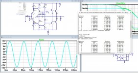
Yes, you are right: that is woefully inadequate.Here's what woefully inadequate looks like.
You are right up to a point: the ultimate proof of a concept lies at the tip of a soldering iron, but the purpose of SPICE work is to gain insights that may not be readily unobtainable with a prototype. Of course, one should always be aware of SPICE's limitations.You could find a more realistic (which does exist, nevertheless) example. I'm sick of these synthetic simulations (here, using ideal current and voltage source for bias) plus the crap models available for free.
I love this audio design approach, coming up with unrealistic numbers from simulation to prove a design, then when confronted with the bench reality: "naaah, you cannot hear these numbers, anyway".
But how else do you compare these things from the basic operation perspective? The models are good enough for a 1st order analysis showing loop behaviour/gain/phase etc between the topologies which is all we are doing here.You could find a more realistic (which does exist, nevertheless) example. I'm sick of these synthetic simulations (here, using ideal current and voltage source for bias) plus the crap models available for free.
I love this audio design approach, coming up with unrealistic numbers from simulation to prove a design, then when confronted with the bench reality: "naaah, you cannot hear these numbers, anyway".
For operation at audio frequencies, most of the LTspice models work remarkably well in predicting distortion, FR, noise etc. I had parasitic oscillation problems on the first version of the kx-Amp, but that issue was ultimately solved using Spice to model the problem (I recall you also initially had stability issues on the PGP).
A lot of the stuff modelled here on the forum by various people has been built and it works well (measured) and is in close agreement with the sims - just root around on the forum.
You are not in a position to talk about 'naah you cannot here the numbers anyway'. Remember your PGP? Could you hear the difference between sub 1ppm and another decent 20 ppm amp?
Worldie (Mikeks) - no point in discussing any of this further with you.
I agree with you on all counts above. SPICE used well gives insights that may be very difficult or impossible to obtain with a practical circuit.But how else do you compare these things from the basic operation perspective? The models are good enough for a 1st order analysis showing loop behaviour/gain/phase etc between the topologies which is all we are doing here.
For operation at audio frequencies, most of the LTspice models work remarkably well in predicting distortion, FR, noise etc. I had parasitic oscillation problems on the first version of the kx-Amp, but that issue was ultimately solved using Spice to model the problem (I recall you also initially had stability issues on the PGP).
A lot of the stuff modelled here on the forum by various people has been built and it works well (measured) and is in close agreement with the sims - just root around on the forum.
A major loop gain of only 56dB at infrasonic frequencies is unacceptably low for an audio frequency amplifier. With a two-stage classical ("voltage feedback") design, major loop gains in excess of 100dB at infrasonic frequencies are readily attainable.Here's what woefully inadequate looks like.
But how else do you compare these things from the basic operation perspective? The models are good enough for a 1st order analysis showing loop behaviour/gain/phase etc between the topologies which is all we are doing here.
For operation at audio frequencies, most of the LTspice models work remarkably well in predicting distortion, FR, noise etc.
Ok, so what does your simulation show? Very low distortion numbers, that you will never get in the real world with that circuit (unless you will find ideal devices, current sources, voltage sources, etc...), nothing more than that.
Yes for FR and noise (and any other small signal metric) nope for most of the large signal metrics (distortions, clipping behavior, load behavior, etc...). In particular at the levels you quoted, that is under 0.0025%, not to mention Dadod's claims of 0.000044%. It would be extremely helpful if, instead simulating the bejeezus out of the same old dusty examples, more effort would be invested in fixing and improving the existing models, in particular for power devices. Something that Andy C (and a very few others) started many years ago, and Mr. Cordell, other than bringing them in a convenient collection, unfortunately did not. The stock models need to be changed structurally, not only adjusting the original parameters. I know, it's not sexy or an otherwise rewarding work.
I’m not condoning any specific numbers that are outrageous and very few of my published designs show ultra low distortion in sim. My amps MEASURE well and that’s what counts. I don’t chase 1 ppm distortion either unless it’s for s marketing reason (sub 10 ppm at 200W).
We’ve both designed and built low distortion high power amps and know the gap between simulation and reality is paved with good intentions and massive implementation potholes and especially so at 10 ppm and below. However, to get a grip on what to tweak, sims are a great tool. It’s also cheap and easy to measure this stuff today and I do that with everything since 2017 when I got my QA401.
(Btw I am using Cordell’s models for the power and diver devices)
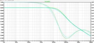
Mike, the loop gain at low frequencies (infrasonic, as you call it) is largely irrelevant. What really matters is the loop gain at HF, in particular at 40KHz and 60KHz, since that’s what helps lowering the 20KHz 2nd and 3rd harmonics. It would be a fair point to compare HF loop gain (with the associated stability margins) at these frequencies.A major loop gain of only 56dB at infrasonic frequencies is unacceptably low for an audio frequency amplifier. With a two-stage classical ("voltage feedback") design, major loop gains in excess of 100dB at infrasonic frequencies are readily attainable.
Hint, which I repeated ad nauseum here: the Maximum Feedback Theorem (aka Bode’s Integral Theorem) and the fact that audio amplifiers are minimum phase systems (that is, small signal linear and time invariant systems) is guaranteeing there is no winner in the CFA vs. VFA game, everything else being equal. And that’s because both are making no assumptions regarding a certain circuit topology or feedback type.
Anything else beyond this fact is fluff, biased opinion, marketing, etc…
One thing I find annoying is that the CFA High Priests are calling “CFA” amplifiers with a diamond buffer input stage and high closed loop gains, making the small signal advantages of the CFA (gain bandwidth independence) vanishingly low. Or calling “CFA” a H-bridge topology, which walks and quacks like a VFA all day and night.
Sometimes you use a CFA design because it solves some other issue that needs to be dealt with.
The market has room for commercial success of all kinds of circuits. I can’t think of a customer ever asking about such a thing.
Feedback or none maybe, but not the type used.
The market has room for commercial success of all kinds of circuits. I can’t think of a customer ever asking about such a thing.
Feedback or none maybe, but not the type used.
And BTW, COD is by no means a property of CFAs as some like to believe (pun intended). A long tail pair VFA can very well be designed with COD, see the Stochino amp with its input stage capacitor cleverly used to dump extra current when required. Other VFA plus COD configuration exist and are liberally used in linear IC designs.
It is the high loop transmission at low frequencies that mitigates things like PSRR and DC offset. This is why, for example, one shouldn't need a DC servo with a competently-designed "voltage feedback" power amplifier.Mike, the loop gain at low frequencies (infrasonic, as you call it) is largely irrelevant. What really matters is the loop gain at HF, in particular at 40KHz and 60KHz, since that’s what helps lowering the 20KHz 2nd and 3rd harmonics. It would be a fair point to compare HF loop gain (with the associated stability margins) at these frequencies.
Moreover, high forward-path gain at high audio frequencies means that there is far greater scope for use of minor loop negative feedback (local feedback) to improve forward-path linearity in a two-stage "voltage feedback" amplifier than exists with a classic single-stage "CFA" without adversely reducing the forward-path gain available to convert to the major negative feedback loop transmission necessary to improve closed-loop linearity.
This means that a competently-designed two-stage "VFA" will have a far more linear forward path than a classic single-stage "CFA" for the same major loop transmission at a given audio frequency. The aphorism "make the amplifier’s forward path as linear as possible before applying major loop negative feedback" springs to mind.
Last edited:
I knew there was a voice of reason around here somewhere. 😀Sometimes you use a CFA design because it solves some other issue that needs to be dealt with.
The market has room for commercial success of all kinds of circuits. I can’t think of a customer ever asking about such a thing.
Feedback or none maybe, but not the type used.
Bonsai, I agree with you on all counts above, and I have a great deal of respect for your practical implementation skills.’ve both designed and built low distortion high power amps and know the gap between simulation and reality is paved with good intentions and massive implementation potholes and especially so at 10 ppm and below. However, to get a grip on what to tweak, sims are a great tool. It’s also cheap and easy to measure this stuff today and I do that with everything since 2017 when I got my QA401.
- Status
- Not open for further replies.
- Home
- Amplifiers
- Solid State
- New book on amplifier design.