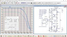
Dadod, congratulations on your design. It appears to be a two-stage design rather than the traditional single-stage CFA. I see you've used a complementary power MOSFET output stage, and this means that your unity major loop gain frequency of 5.5MHz is tenable because the gain-bandwidth product of a power MOSFET is at least ten times that of a power bipolar transistor. A complementary power MOSFET output stage may, therefore, be subjected to more loop transmission than a complementary bipolar transistor output stage. Regrettably, however, the transconductance of a power MOSFET is typically an order of magnitude smaller than that of a bipolar power transistor, and, consequently, a complementary power MOSFET output stage is likely to be at least an order of magnitude less linear than a complementary bipolar transistor output stage given the same loop transmission. Thus, the extra loop transmission, 90dB in your case, afforded by the superior gain-bandwidth product of the power MOSFET output stage is necessary to mitigate the output stage's non-linearity.
A unity major loop gain frequency of 5.5MHz would be unsustainable with a bipolar power transistor output stage because of the mediocre current-gain bandwidth product of the output transistors. Moreover, the current-gain-bandwidth product of a bipolar power transistor falls precipitously at high and low collector currents while peaking at some median collector current. Therefore, the current-gain-bandwidth products of the power transistors in a complementary bipolar transistor output stage vary dynamically with collector current, and, consequently, the output stage’s dominant pole will likewise vary with the current demanded by the amplifier’s load. This should be taken into account when selecting the unity major loop gain frequency of the amplifier.
A unity major loop gain frequency of 5.5MHz would be unsustainable with a bipolar power transistor output stage because of the mediocre current-gain bandwidth product of the output transistors. Moreover, the current-gain-bandwidth product of a bipolar power transistor falls precipitously at high and low collector currents while peaking at some median collector current. Therefore, the current-gain-bandwidth products of the power transistors in a complementary bipolar transistor output stage vary dynamically with collector current, and, consequently, the output stage’s dominant pole will likewise vary with the current demanded by the amplifier’s load. This should be taken into account when selecting the unity major loop gain frequency of the amplifier.
Last edited:
"Therefore, the current-gain-bandwidth products of the power transistors in a complementary bipolar transistor output stage vary dynamically with collector current . . ."
They do, but there's a fix for that - an EF3. Its more complex than a mosfet OPS, but there are always solutions for these problems based on the designer's OPS device selection. You either have the bandwidth afforded by mosfet's but deal with the lower transconductance or you deal with the lower fT of bipolars and take the improved transconductance.
This is all a moot point however, since layout quickly ultimately determines the maximum BW you can employ given the reactive load audio amps have to contend with.
On the contrary, it is, in fact, the gain bandwidth product of the output devices that is the primary delimiter of the bandwidth of the output stage, irrespective of the selected configuration. This is also true of the triple output stage. In the case of a bipolar output stage, this is exacerbated by the fact that the current-gain bandwidth product of the bipolar power transistors varies dramatically with current. Note that the drivers' gain bandwidth product should not be a concern since it is, or should be, typically in the high tens to hundreds of megahertz."Therefore, the current-gain-bandwidth products of the power transistors in a complementary bipolar transistor output stage vary dynamically with collector current . . ."
They do, but there's a fix for that - an EF3. Its more complex than a mosfet OPS, but there are always solutions for these problems based on the designer's OPS device selection. You either have the bandwidth afforded by mosfet's but deal with the lower transconductance or you deal with the lower fT of bipolars and take the improved transconductance.
This is all a moot point however, since layout quickly ultimately determines the maximum BW you can employ given the reactive load audio amps have to contend with.
Interesting, now you appear to shift your position to a more rational approach. Few years ago, during our hot debate, you protested when I mentioned exactly the same, and you claimed "current feedback" as something that escapes the common feedback types and analysis methodology. Not even a 10 page of math showing how to identify the "magic" CFA properties using standard feedback circuit analysis didn't move you a iota from your trenches. Need me to dig into the archives?Its simply an amplifier topology that happens to possess certain characteristics just like a VFA has certain characteristics.
As of Dadod's amplifier, I hate I have to mention this again: this amplifier is the result of Spice tweaking a basic topology, disregarding any secondary potential stability issues, much like handling TMC as a single pole compensation schema. I would not touch such an amplifier with 6MHz ULGF with a 10 feet pole, until each and every feedback minor loops are analyzed and their properties (in particular with difficult loads) are identified, quantified and optimized (if possible). In particular because higher order compensations up to a reasonable order of 5 (like in the Purifi amplifiers, doesn't matter they are class D) are available and can be systematically designed, without needing a crazy ULGF. The commercial amplifier with the highest ULGF that I have seen was short of 2MHz (I think it was an Accuphase), anybody wonders why nobody went higher?
Secondly, Dadod always chooses to characterize his amplifiers at an output level with a generous reserve toward the rails. This is a super optimistic case, both in simulation and practice, since it is approaching the rails is the worst case for both the output distortions and potential stability issues. I am afraid designing an amplifier assuming it will never approach the rails is a recipe for disaster; I've seen enough otherwise excellent amplifiers that distort badly (mean an order of magnitude or more, over the "happy path") or even self distruct at a short overload.
I agree and I seem to remember that I have mentioned the same thing a few times myself, but with no luck.As of Dadod's amplifier, I hate I have to mention this again: this amplifier is the result of Spice tweaking a basic topology, disregarding any secondary potential stability issues, much like handling TMC as a single pole compensation schema. I would not touch such an amplifier with 6MHz ULGF with a 10 feet pole, until each and every feedback minor loops are analyzed and their properties (in particular with difficult loads) are identified, quantified and optimized (if possible). In particular because higher order compensations up to a reasonable order of 5 (like in the Purifi amplifiers, doesn't matter they are class D) are available and can be systematically designed, without needing a crazy ULGF. The commercial amplifier with the highest ULGF that I have seen was short of 2MHz (I think it was an Accuphase), anybody wonders why nobody went higher?
Secondly, Dadod always chooses to characterize his amplifiers at an output level with a generous reserve toward the rails. This is a super optimistic case, both in simulation and practice, since it is approaching the rails is the worst case for both the output distortions and potential stability issues. I am afraid designing an amplifier assuming it will never approach the rails is a recipe for disaster; I've seen enough otherwise excellent amplifiers that distort badly (mean an order of magnitude or more, over the "happy path") or even self distruct at a short overload.
Stein
Nonsense. You are confusing me with others. I personally have never claimed magical properties for the CFA - simply pointing out where is performed better and doing the same on VFA too btw. I hosted the CFA vs VFA thread way back and made an honest attempt to be scrupulously even handed on the subject. Unfortunately that thread turned into an utter farce because at every turn there were those claiming it was just a VFA and others indeed claiming magical properties for CFA - one member in particular who has now removed himself from the forum. We could never get a rational discussion going and it eventually degenerated into an ugly slinging match and had to be closed down.
I cannot comment on dadod’s design approach- I merely used it to point out that claims that CFA’s have a ‘paucity’ of gain are not correct.
I cannot comment on dadod’s design approach- I merely used it to point out that claims that CFA’s have a ‘paucity’ of gain are not correct.
Last edited:
No, not really, since there’s more here than the gm drop. Things like high level charge injection effects (such as emitter crowding), large signal base charge recombination, etc…things that are not really modelled in the dumb device models available for free.A good EF3 stage will see distortion hardly change from 2 Ohms to 16 Ohms
What were you hosting? I thought it was just a thread on this forum? No I don’t confuse anything, archive search in progress, you seem to need some reminders.Nonsense. You are confusing me with others. I have never claimed magical properties for the CFA. I hosted the CFA vs VFA thread way back that turned into an utter farce because at every turn there were those claiming it was just a VFA of others indeed claiming magical properties for CFA - one member in particular who has now removed himself from the forum. We could never get a rational discussion going
And CFAs do have “magic“ (or unique, or counter intuitive) properties compared to other topologies
Here’s a nice summary of your stances on CFA, dismantled. Side note, you seem to use the “confusing me with others” quite often.Nonsense. You are confusing me with others.
https://www.diyaudio.com/community/...semantic-problem.311005/page-118#post-5658407
The current demanded by a given load and, therefore, the current through the output devices does not change simply because you choose to use a triple instead of, say, a double output stage. The gain-bandwidth product of a transistor is a function of the current through the transistor for a given voltage across it.Of course they do - and the result is the gain drops off with load current. The EF3 reduces that effect. A good EF3 stage will see distortion hardly change from 2 Ohms to 16 Ohms
Given the same output devices, compared with, say, a double output stage, the linearity of the triple in the face of adverse loads has virtually nothing to do with the gain bandwidth product of the output devices. Therefore, the bandwidth of the output stage is more a function of the gain bandwidth product of the output devices than the configuration of the output stage.
It appears that you are conflating how a power BJT sustains beta at DC with its current-gain bandwidth product. The two are not necessarily related.
Last edited:
Notwithstanding Dadod's two-stage offering, I still maintain that the standard "CFA" is useless as a linear audio frequency amplifier principally because its forward-path gain is only that of a single common-emitter stage. This means that this topology does not generate anywhere near enough loop gain to mitigate its own non-linearity, never mind that of the output stage to which it is attached.
Here’s what I wrote about CFA - a simple primer to address the questions that came up in the thread
https://hifisonix.com/current-feedback-amplifer-vs-voltage-feedback-amplifier/
https://hifisonix.com/current-feedback-amplifer-vs-voltage-feedback-amplifier/
I am simply claiming that to mitigate the gain droop apparent in a bipolar OPS, you can use an EF3. We can get into a circular semantic exchange but that of course leads to nowhere.
"Notwithstanding Dadod's two-stage offering, I still maintain that the standard "CFA" is useless as a linear audio frequency amplifier principally because its forward-path gain is only that of a single common-emitter stage. This means that this topology does not generate anywhere near enough loop gain to mitigate its own non-linearity, never mind that of the output stage to which it is attached."
Its difficult to take statements like this seriously. (Dadod's is not the only high loop gain CFA out their BTW)
")
"Notwithstanding Dadod's two-stage offering, I still maintain that the standard "CFA" is useless as a linear audio frequency amplifier principally because its forward-path gain is only that of a single common-emitter stage. This means that this topology does not generate anywhere near enough loop gain to mitigate its own non-linearity, never mind that of the output stage to which it is attached."
Its difficult to take statements like this seriously. (Dadod's is not the only high loop gain CFA out their BTW)
Sorry, I see nothing - just a link to a thread.Here’s a nice summary of your stances on CFA, dismantled. Side note, you seem to use the “confusing me with others” quite often.
https://www.diyaudio.com/community/...semantic-problem.311005/page-118#post-5658407
If you sim EF, EF2 and EF3 side by side there is about a 2 orders of mag improvement towards EF3 with loads going from 2-16 Ohms.No, not really, since there’s more here than the gm drop. Things like high level charge injection effects (such as emitter crowding), large signal base charge recombination, etc…things that are not really modelled in the dumb device models available for free.
If you measure it, the variation in distortion is around 10x better in the EF3 vs EF2. On a big 6 pair power amp, the distortion at close to full power varies from c. 10ppm to 70ppm going from 2 > 8 Ohms. you will not get those figures with EF or EF2.
The point is, EF3 offers a significant improvement over EF2 - sim'd and measured. Cordell and Self both discuss this in their books.
Notwithstanding Dadod's two-stage offering, I still maintain that the standard "CFA" is useless as a linear audio frequency amplifier principally because its forward-path gain is only that of a single common-emitter stage. This means that this topology does not generate anywhere near enough loop gain to mitigate its own non-linearity, never mind that of the output stage to which it is attached.
If you meant that VAS/TIS is only stage with gain it is not so, IPS has gain too, look AC plot of this CFA IPS with passive load and overall amp LG is flat up to 20 kHz.
syn08 was always afraid of high ULGF, not sure way, probably never tried to build real amp with ULGF higher then 1 MHz.
Example showed here earlier was an amp with active load as an example how high LG can a CFA have. I did not build it yet, and would probably use more conservative approach wit ULGF between 2 and 3 MHz I used in my already built amps. Many others in this forum built 100W version with no stability problems.
To protect my amps and loudspeaker from catastrophic failure I use a kind of power supply with overcurrent, DC offset and unsymmetrical voltage. Idea used came from JLH 80 W mosfet amp. Now in addition I use SSR at the amp output too.
Problem RMarsh had with the amp in Thailand was missing any kind of protection, I suggested to use my PS regulator(kind of cap multiplier) with incorporated protections, but thy want listen. CFA power amps with that high SR are, in my opinion, more prone to input disturbances like fast DC impulses, so protection is essential.
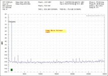
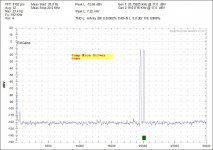
I attache real FFT measurement of my CFA amp(serial combination of ClassA and ClassB) to show that CFA can have quite low distortion.
Damir
below are some post from 200W mosfet CFA thread.
**********************************
Manso post
I dont know what to make of the rather strange phase behavior but I posted months ago about the findings by the designers at TI. They have obviously studied such behavior with their opamps and their conclusion was that stable inner or local loop phase behavior is not a requirement for overall stability. What is important is the outer feedback loop. See their datasheets on various opamps, its clearly stated in nearly all of the newer designs. Ive come to the same conclusion with my amps. Many of the so called gurus here will tell you otherwise but the truth is they should rather argue their case with the actual designers like those from TI which place actual working products on the market.
dadod post
In my opinion all the inner loops instability should be seen in the global (outer) loop
HarryDymond post
Unfortunately this is not true.
It’s fairly easy to make a two-pole compensated amp where the outer loop looks fine but the inner loop is unstable (put cascodes in the input stage and VAS/TIS, beta-enhance the VAS/TIS, connect feedback caps so both casodes are included in the loop).
This is an issue that was brought to my attention when I published my two-pole compensation paper. Some people were unimpressed that I had suggested adding cascodes and including them in the inner loop (to improved PSRR), without addressing the stability of that loop. It was true that I hadn’t thought to check this, and sure enough, although the global loop was well stable with ample gain and phase margins, the inner loop was not stable! A judiciously placed series RC to ground in the inner loop can usually solve this problem.
Presumably inner loop instability would manifest in a time-domain simulation in one way or another, but it is demonstrably false that inner loop stability can be assured by looking at a bode plot of the outer loop loop gain.
but then HarryDymond post
Apologies to Dadod and others - I had misremembered my simulations from before. You can indeed “see” the effects of inner loop instability in a bode plot of the outer loop loop gain - the main loop is stable, but has an unpleasant-looking peak exactly at the unstable frequency of the inner loop. See attached images showing comparison of when the inner loop is compensated vs not (A1/B1 plots = inner loop not compensated, A2/B2 plots = inner loop compensated, A plots = outer loop loop gain, B plots = inner loop loop gain).
Attachments
And my point is you are conflating DC beta versus current with current-gain bandwidth product, which are not related. You cannot mitigate current-gain bandwidth product by using a triple. You can only improve the bandwidth of the output stage by increasing the number of output devices in parallel to reduce the amount of current demanded of each device. Unfortunately, this still doesn't account for the current-gain bandwidth droop at low device currents.I am simply claiming that to mitigate the gain droop apparent in a bipolar OPS, you can use an EF3.
Last edited:
- Status
- Not open for further replies.
- Home
- Amplifiers
- Solid State
- New book on amplifier design.