Wow this is very surprising to me! I wonder if the capacitors are shunting the non-linear supply current to ground, and its showing up in the output because of the non-zero ground impedance? The fact that it's predominantly 3rd harmonic suggests that maybe these capacitors have a significant voltage coefficient?
That sounds like a good theory! I've been pondering how something on the power rails could wind up present on the output, given the PSRR of the chip.
Although the batteries have a higher impedance than the capqditor that battery impedance may be fairly constant through the audio band. With the electrolytics in place they should bypass the batteries, since they are low ESR, but the capacitor impedance may not be as flat through the band.
I believe that I have some 22uF 16V X7R MLCC caps that would fit just fine in the same holes. Tomorrow I'll extract the electros and re-test with the ceramics. Lol - poke the system and see how it responds. 🙂 I know that X7R is going to be a bit voltage sensitive.
The OPA1688 is a mighty good sounding chip! I've listened to several hours worth of music with the chip now.
Last edited:
Well I found the problem! The large harmonics are not due to the rail electrolytics after all. Somehow I managed to damage one channel of the OPA1688 chip around the time I installed the electrolytics, which is the source of that huge 3rd harmonic when the 32R load is attached. The other channel of the chip works just fine.
How I tracked this down was swapping the 22uF rail electros for 22uF X7R MLCCs. The results were exactly the same as with the electrolytics, the huge 3rd harmonic, which seemed very fishy. Then I bypassed the solid state relays between the batteries and the circuit thinking maybe that was a source, even though they are just 0.05R on. Well no effect, 3rd harmonic still there. So then I removed the 22uF MLCCs so it was back to no capacitors on the power rails and....3rd harmonic still there! Oops. Then I tried using the other channel of the chip and all is OK.
I've been doing quite a bit of testing of various types with the chip and board over the last week. I have no doubt the fault was mine at some point in damaging the chip. I use a grounded antistatic mat, wrist strap, iron tip, antistat tool grips, etc., but there is also a cat wandering around which kind of negates the whole antistat effort. 😛
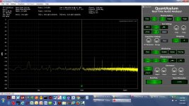
At any rate here is a re-do below with the other channel on the OPA1688 chip. The previous 22uF power rail electros are soldered back in and the battery SSRs back in place un-bypassed. Same 32 ohm load. The input levels of the 3 are -10dBV, -1dBV and 3dBV. Looks great. 🙂 Again keep in mind this particular model of THD analyzer has significant 2nd and 3rd harmonics itself at higher levels, so the results from the chip are really pretty darn good, especially with the 32R load.
The rail eletrolytics after the power supply SSRs still do seem to make the turn-on turn-off pops more prominant, which was the whole point in trying them, so I'll probably be leaving them off the final board spin. Seems that just having the rails turn-on and cut-off as soon as possible with the SSRs is better than allowing the rails to linger with the electros on them, from a pop-reduction standpont.
How I tracked this down was swapping the 22uF rail electros for 22uF X7R MLCCs. The results were exactly the same as with the electrolytics, the huge 3rd harmonic, which seemed very fishy. Then I bypassed the solid state relays between the batteries and the circuit thinking maybe that was a source, even though they are just 0.05R on. Well no effect, 3rd harmonic still there. So then I removed the 22uF MLCCs so it was back to no capacitors on the power rails and....3rd harmonic still there! Oops. Then I tried using the other channel of the chip and all is OK.
I've been doing quite a bit of testing of various types with the chip and board over the last week. I have no doubt the fault was mine at some point in damaging the chip. I use a grounded antistatic mat, wrist strap, iron tip, antistat tool grips, etc., but there is also a cat wandering around which kind of negates the whole antistat effort. 😛
At any rate here is a re-do below with the other channel on the OPA1688 chip. The previous 22uF power rail electros are soldered back in and the battery SSRs back in place un-bypassed. Same 32 ohm load. The input levels of the 3 are -10dBV, -1dBV and 3dBV. Looks great. 🙂 Again keep in mind this particular model of THD analyzer has significant 2nd and 3rd harmonics itself at higher levels, so the results from the chip are really pretty darn good, especially with the 32R load.
The rail eletrolytics after the power supply SSRs still do seem to make the turn-on turn-off pops more prominant, which was the whole point in trying them, so I'll probably be leaving them off the final board spin. Seems that just having the rails turn-on and cut-off as soon as possible with the SSRs is better than allowing the rails to linger with the electros on them, from a pop-reduction standpont.
Attachments
Last edited:
Now this makes more sense! You're previous post was a bit of a head-scratcher for me because I had previously never seen rail capacitors add distortion. And normally distortion from power supplies tends to add even harmonics, not odd. But when it comes to debugging distortion, I try to keep an open mind.
The new measurements look great. I actually have a QA400 analyzer so I'm aware of the harmonics that pop up at 0 dBV and greater signals (still a great piece of equipment). It would be interesting to see how the OPA2134 compares in the same circuit, since that seems to be the op amp most commonly selected for CMOY headphone amps (despite not being particularly well-suited for low impedance loads).
Enjoy!
Just suppress the main tone, one or the other way, and you will be happy for the rest of your life. 🙂
Now this makes more sense!
I agree! 🙂 This one had me going. Interesting thing, the "bad" channel sounds just fine listening to music. That is what makes me think it is static damage. From past experience it seems that mild static damage, or small overvoltage, may alter a few chip specifications but otherwise leave a chip functional, but with a short(er) lifespan.
Hey I like that idea of building one up with the OPA2134! I'll do it. I had a bunch of these boards come back from fab. It will be really interesting to see what the OPA2134 does with a 32R load. Probably not a happy camper with much over 0.7Vrms out, which should be around 31mA peak if I've done the math right.
Just suppress the main tone, one or the other way, and you will be happy for the rest of your life. 🙂
I'm trying! 😀 Fliege notch filter
http://www.diyaudio.com/forums/equipment-tools/284202-fliege-1khz-notch-filter-project-pcb.html
and Akerberg-Mossberg differential notch
http://www.diyaudio.com/forums/equi...g-fully-differential-notch-q401-part-1-a.html
So far the only chips the Fliege doesn't oscillate with are the THS4032 from the original TI paper and the AD8397, DSL line drivers. I was testing the AD8397 version last night and it produces a 2nd harmonic that is larger than the QA401's. 😛
I also have a twin-T laid out if all else fails. 🙂
Last edited:
Notch is not the only way, and definitely not th handiest one.
Baxandall was writing about this ages ago, but it it known for more than that. It it more like a variety of wheatstone bridge.
Baxandall was writing about this ages ago, but it it known for more than that. It it more like a variety of wheatstone bridge.
Last edited:
Notch is not the only way, and definitely not th handiest one.
Hmm.... you are right, come to think of it! If what I've looking at are the harmonics above the fundamental then a 2nd or 3rd order high pass filter, with a steep slope, should do the job. Or if I'm looking at 2-tone IMD a low pass filter should work. That would certainly take the criticality out of exactly lining the a notch filter with the fundamental frequency. Just pick Butterworth or other type of HPF/LPF with a fairly flat passband.
I was wondering about that. Even a 3rd order HPF might not be sharp enough to prevent the 2nd (and possibly 3rd) harmonic from getting nuked.
Lol I'm into weird solutions for things. They are more interesting. 😀 How about mixing an inverted copy of the fundamental in after the DUT but before the THD analyzer? Time delayed if necessary, and probably PLL phase locked to prevent producing beat frequencies. Here is a somewhat similar discussion for AC power system harmonics and cancelling them with out-of-phase-copies (opens PDF):
www.controlledpwr.com/whitepapers/ukphsta2.pd
Last edited:
OPA1689...
johnc124 - in reading through the OPA1688 datasheet again just now I noticed the OPA1689, in a quad SOIC14, and the "better idea" light bulb went on. 😀 The OPA1689 doesn't appear to be shipping yet, do you know if it is sampling?
I'm assuming that I could parallel the outputs on each half of the 1689 via 1 ohm or so for 140-150mA? If so that gets me all excited, lol. 😛 That would be right up there with the O2 headamp at 140mA per channel. I'm assuming that two single SOIC8s could dissipate more power though than a single SOIC14. Any rough guesses how much difference in dissipation ability between the two packages (SOIC8 and SOIC14)? And given however things are laid out inside the 1689, any benefits to paralleling it down each side (pin 1 + pin 7 though 1R's) vs. side to side (pin 1 + pin 14)?
The data sheet lists Iq as 1.6mA nominal per amp, so I'm assuming that for the 1689 that would still be the 4 * 1.6mA? If so the quiescent current would still be less than just the (dual) gain-stage NJM2068 Iq in the O2 headamp, without even adding in the two unity gain NJM4556As' Iq or the NJM2903 comparator chip.
Thanks for the info!
Last edited:
How about mixing an inverted copy of the fundamental in after the DUT but before the THD analyzer?
Finally you are on the right track, after a few years of hinting it to you 🙂
What do you think I meant when I mentioned Wheatstone bridge? 😀
Requirement for accuracy of the subtraction much more relaxed if you are using at least half decent sig gen and FFT analyzer. Also it is very easy to implement for some cases.
Although you have to pay an attention that what you observe is a product of the DUT but not elements of the bridge.
Do you want me to cut it straight to the schematic?
Last edited:
Do you want me to cut it straight to the schematic?
I finally figured it out! 😀 Absolutely, hit me with the schematic, lets see how this works. 🙂
Also I just noticed that I messed up my link in #31 above, the f in pdf at the end got cut off. Just paste it in a browser and add an f to the end to make it work.
Last edited:
OK, will start from a bit more simple case where you are evaluating an inverting circuit. With non-inverting it will need an extra inverter.
Case "a" is a simplified variant. It works fine when you have your gain ~-1. Error signal attenuation is going to be significant if DUT configured with a higher gain.
Case "b" is a tiny bit more complicated, but also provides some gain if needed. You don't need a very good opamp for this, since the signal it will work with is very small. 5534 if a good choice if input currents are not a problem.
You can add a trimpot and some phase shifting stuff to the error selector branch to minimize main tone and harmonics creep from you signal source. Just make sure that both opamps are happy and stable with given Z's.
Make sure that resistors you are using are good and to not distort under given conditions. Also if your Za = Zb and Zc = Zd, you can get some cancellation of this type of distortion, if it is a problem.
You can change Ze a bit, adding a small C, if opamp is unstable.
Keep in mind that Z's in the schematic can be more complicated than shown. They can be represented by T or Pi nets. This will make formulas more complicated, but not too hard to figure that out.
Last edited:
It would be interesting to see how the OPA2134 compares in the same circuit, since that seems to be the op amp most commonly selected for CMOY headphone amps (despite not being particularly well-suited for low impedance loads).
Here is the answer. 🙂
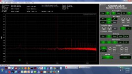
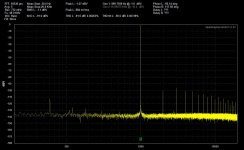
I've replaced the OPA1688 chip with the damaged channel with a new one, on one board, then built up a second identical board with an OPA2134UA instead of the OPA1688. Luckily the pinout is the same. I'm going through the plots here from left to right and top to bottom in the discussion. Mousing over the plots will also bring up the file name that has the parameters.
* The first two plots on the top row are the OPA1688 board with no load and the OPA2134 board with no load, both at -10dBV in and (amp adjusted for) out.
* The next two plots on the top row are the OPA1688 board with a 150R resistive load and the OPA2134 board with a 150R resistive load, both at -10dBV in and (amp adjusted for) out.
* The next two plots are the OPA1688 board with a 32R resistive load and the OPA2134 board with a 32R resistive load, both at -10dBV in and (amp adjusted for) out.
* The next two plots are the OPA1688 board with a 150R resistive load and the OPA2134 board with a 150R resistive load, both at -1dBV in and (amp adjusted for) out.
* The final two plots are the OPA1688 board with a 32R resistive load and the OPA2134 board with a 32R resistive load, both at -1dBV in and (amp adjusted for) out.
The OPA2134 generates substantially more harmonics, as expected, especially at the -1dBV drive level and heavy 32R load. Lol the OPA2134 was getting hot enough with the -1dBV/32R test conditions that I only left the load connected for about 10 seconds to take the screenshot. The OPA1688 didn't have that dissipation problem at -1dBV/32R.
Attachments
-
 32R resistive load -1dBV in_out on OPA2134 CMOY red channel.jpg231.8 KB · Views: 182
 -
 32R resistive load -1dBV in_out on OPA1688 CMOY red channel.jpg232.5 KB · Views: 176
 -
 150R resistive load -1dBV in_out on OPA2134 CMOY red channel.jpg230.8 KB · Views: 147
 -
 150R resistive load -1dBV in_out on OPA1688 CMOY red channel.jpg233.9 KB · Views: 150
 -
 32R resistive load -10dBV in_out on OPA2134 CMOY red channel.jpg233.3 KB · Views: 145
 -
 32R resistive load -10dBV in_out on OPA1688 CMOY red channel.jpg233.2 KB · Views: 168
 -
 150R resistive load -10dBV in_out on OPA2134 CMOY red channel.jpg232.3 KB · Views: 603
 -
 150R resistive load -10dBV in_out on OPA1688 CMOY red channel.jpg232.6 KB · Views: 600
 -
 no load -10dBV in_out on OPA2134 CMOY red channel.jpg234.7 KB · Views: 617
 -
 no load -10dBV in_out on OPA1688 CMOY red channel.jpg232.9 KB · Views: 637
Last edited:
Hmm, the OPA2134 getting hot makes me suspicious that it wasn't stable. Did you check the output for oscillation with an oscilloscope? Maybe doing a small signal square wave test?
The increased harmonics on the OPA2134 isn't a surprise though.
Edit: Alternatively, a good first check might be just measuring the DC offset at the output.
The increased harmonics on the OPA2134 isn't a surprise though.
Edit: Alternatively, a good first check might be just measuring the DC offset at the output.
The two op-amps differ in quiescent current. That difference is about 4mA total/package. Thus the total difference in quiescent dissipation will be 4mA * your total supply voltage. In your application that should be the only difference in power consumption between the two amps. The dissipation that occurs in the devices as a result of driving the load will be identical and likely the majority of the difference. If the OPA2134 is significantly hotter something else is going on -- mis-wiring or oscillation.
Edit: I assume you're using the same package for both parts -- e.g., a '1688 with thermal pad soldered to a PCB with a good ground/power plane will not get as hot as an OPA2134 which doesn't have this. If both are in SOIC as I suspect, then the above comments apply
Edit: I assume you're using the same package for both parts -- e.g., a '1688 with thermal pad soldered to a PCB with a good ground/power plane will not get as hot as an OPA2134 which doesn't have this. If both are in SOIC as I suspect, then the above comments apply
Last edited:
Hmm, the OPA2134 getting hot makes me suspicious that it wasn't stable. Did you check the output for oscillation with an oscilloscope? Maybe doing a small signal square wave test?
Entirely possible! I'll whip out the scope in a day or two and check. I used your 47pF for compensation on both. That was going through my head at the time that 47pF may not (probably not) won't be enough compensation for the OPA2134. I figured I would start with the 47 then go up if it oscillates.
I should leave it running longer with the 32R load too and use my mini-IR gauge or a thermocouple to find out how hot it really is. The heat level is probably OK, hot but not at "burn the finger" level, at least after just 10 seconds. 🙂 Lol I just chickened out after 10 seconds because I wanted to get a set of tests results recorded before anything fried and I had to take time to replace a chip. 😛
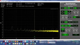
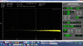
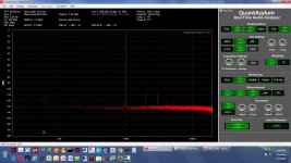
So attached below is the "reality" of rail electrolytics vs. my previous post, they do actually seem to reduce some harmonic distortion products, especially when the OPA1688 chip is run with heavy (32R) loads. I received the capacitors I had intended to use on the board from Mouser (the prior 22uF was something I had on hand). These plots are with a 100uF 16V solid organic polymer electro with a very low 35mR ESR (Mouser #647-RNE1C101MDS1PX). Then I also received some more conventional 100uF low 300mR ESR electros in the same form-factor that I haven't tried yet but will (Mouser #667-EEU-FR1C101B).
The testing effort hit a speed-bump when I discovered (another thread) that the QA401 in loopback had considerably higher THD on the left channel than right. Some email exchange with the manufacturer ensured and it turns out that is a known thing, the fault of the DAC being used at the 192Ksps sample rate I was using at the time. It doesn't do that at 48Ksps (much lower 2nd and 3rd harmonics at around -123dB vs -117 at 192Ksps) and they recommend using 48Ksps. The good news is the right channel is still pretty good at 192Ksps, and that is why the plots in post #37 above are red - red is right channel in the QA401. So all of this is why the plots below are now done at 48Ksps rather than the prior 192Ksps. 🙂
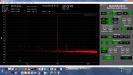
The first plot is with no electrolytics at all on the power rails, 48Ksps sampling, 65K window, -1dBV input and the output adjusted for -1dBV. The second is the same but with a 100uF solid organic polymer cap on each rail. If the 9V battery has 3 ohms of internal resistance that would be around 500Hz for the 100uF caps. Useful from 500Hz and up most likely. At 1KHz they would be around 1.6 ohms. The THD numbers are up at the top. -91.6dB THD without rail caps, -99.3 with.
I assume you're using the same package for both parts -- e.g., a '1688 with thermal pad soldered to a PCB with a good ground/power plane will not get as hot as an OPA2134 which doesn't have this. If both are in SOIC as I suspect, then the above comments apply
No thermal pad on the OPA1688, interestingly enough! I just took a look at one to make sure. I have made that mistake before though. On V1.0 of a Fliege notch filter project here I used LME49880s which do have a thermal pad that I forgot about. I placed two traces right under the chip. 😱 A do-it-yourself capacitor between the traces via the solder mask.
You are right, there is a 2mA or so difference per amplifier in Iq between the chips, which should be somewhere around 2mA * (9V - (-9V)) * 2 amps = 72mW of extra idle dissipation in the old OPA2134.
Attachments

Last edited:
- Status
- Not open for further replies.
- Home
- Vendor's Bazaar
- New Audio Op Amp - OPA1688