LM4702 and LME49810 based amplifiers. they are class AB amplifiers, but the audio performance is well above the audiophile range.
for low-medium power applications i recommend LM4702+SAP15 amplifier, http://connexelectronic.com/product...ducts_id/77?osCsid=ls1k04v5ei3h1vn9bc9sqsb7m4
for medium power application i recommend LM4702 BPL amplifier http://connexelectronic.com/product...ducts_id/76?osCsid=ls1k04v5ei3h1vn9bc9sqsb7m4 there is a version with heatsink included, or LM4702 MOS http://connexelectronic.com/product...ducts_id/75?osCsid=ls1k04v5ei3h1vn9bc9sqsb7m4 also has a version with heatsink.
for medium to high power i recommend LME49810 based amplifiers, the 300W version: http://connexelectronic.com/product...ducts_id/74?osCsid=ls1k04v5ei3h1vn9bc9sqsb7m4 and the 500W version: http://connexelectronic.com/product...ducts_id/78?osCsid=ls1k04v5ei3h1vn9bc9sqsb7m4 heatsink available for all models.
for best performance i also recommend a 4 rails power supply, for smaller power the http://connexelectronic.com/product_info.php/products_id/96?osCsid=ls1k04v5ei3h1vn9bc9sqsb7m4 power supply and for bigger power (300-500W) this power supply: http://connexelectronic.com/product_info.php/products_id/93?osCsid=ls1k04v5ei3h1vn9bc9sqsb7m4 the amplifiers use 4 rails for better performaces and signal to noise ratio.
the speaker protection circuit is not required for LME49810 based amps, since there is implemented already on the board, just for lower power models. but the powersoftstart is recommended to be used esspecially for the power supply with 6 pcs 18000uF capacitors. the inrush current of this capacitors is huge, and will lead to mains fuse trip durring power on if there is no current limit. the board has a total capacity of 108mF and they can store a huge energy, 270 Joules.
Hi Cnx,
Finally manage to connect everything, but I still have issues testing the amp (TA2022). What happens :
- the two leds are on => means mute is on if I understood well
- the speakers make a small ploc when putting the amp on
- after that, no sound at all comes out of the speakers :-(
I'm pretty sure of my connections, except for one point : on the input connector, which one is 1 and which one is 9. Could you confirm with this picture ?
Attachments
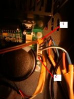
for the TA2022 amplifier pin 1 is the square one, so like in your picture. i cannot see where the wires go.
one important thing which you need to check, i wrote about in the manual also. the amplifier will enter in mute mode when the supply voltage is either lower or higher than the normal range, +-25 to +-33V. measure the voltage values of both rails. also measure the output DC offset without load. it should be lower than 10mV. i adjusted for all amplifiers before testin and shipping, but durring the installation is very possible to touch the variable resistors for DC offset cancellation and to alter the setting. an DC offset higher than 150-200mV with load connected will automatically lead to voltage pumping and amplifier mute. so, disconnect the load and turn on the amp. if this is the problem, the red led will not light after turn on and you will have a DC offset higher than previous mentioned value.
one important thing which you need to check, i wrote about in the manual also. the amplifier will enter in mute mode when the supply voltage is either lower or higher than the normal range, +-25 to +-33V. measure the voltage values of both rails. also measure the output DC offset without load. it should be lower than 10mV. i adjusted for all amplifiers before testin and shipping, but durring the installation is very possible to touch the variable resistors for DC offset cancellation and to alter the setting. an DC offset higher than 150-200mV with load connected will automatically lead to voltage pumping and amplifier mute. so, disconnect the load and turn on the amp. if this is the problem, the red led will not light after turn on and you will have a DC offset higher than previous mentioned value.
OK, I will check these. Thanks for the answer.
One precision : the LED is orange and not red in my cas, but I imagine it's the same one ;-)
One precision : the LED is orange and not red in my cas, but I imagine it's the same one ;-)
Is it any point to invert the signal in an Behringer DCX2496 before it goes to the amp?I run it as two way.if the phase of the input signal is inverted with 180* at one channel with respect to the other, then the amplifier performace and stability is improoved do to the pumping effect compensation.
as i mentioned in your quote, the inverted signal on one channel will compensate almost complete the pumping effect which have negative influence on the amplifier performance, stability and reliability.
romtom: your amplifier is from a batch in wich i used orange LED's instead of red. there is another batch in which i used blue LED for power and Orange for Fault.
romtom: your amplifier is from a batch in wich i used orange LED's instead of red. there is another batch in which i used blue LED for power and Orange for Fault.
Cristi,
which transformer rating would you recommend for your TA2022 amp: 2*24V @6.6A or 8.3A? Will the smaller one be enough?
Wolfram
which transformer rating would you recommend for your TA2022 amp: 2*24V @6.6A or 8.3A? Will the smaller one be enough?
Wolfram
6.6A ~=300VA and will supply 150W to 300W of total maximum audio power.2*24V @6.6A or 8.3A?
8.3A ~=400VA and will supply 200W to 400W of total maximum audio power.
Hi cnx
I am new to this forums. I place an order yesterday for 2 TA2022 Amp and got a paypal confirmation for my payment. Please check if you got my order. Thanks
I am new to this forums. I place an order yesterday for 2 TA2022 Amp and got a paypal confirmation for my payment. Please check if you got my order. Thanks
Cristi,
which transformer rating would you recommend for your TA2022 amp: 2*24V @6.6A or 8.3A? Will the smaller one be enough?
Wolfram
2*24V @ 6.6A is ~320VA not 160VA.Forgot to mention: the smaller one has 160VA, the other one 200VA
How are you coming to your data and calculations?
Probably I made a mistake then. The datasheet at RS components says:Sek current 6,667 A/ output VA160. The transformer is made by Nuvotem.
Cristi,
which transformer rating would you recommend for your TA2022 amp: 2*24V @6.6A or 8.3A? Will the smaller one be enough?
Wolfram
the 6.6A is enough for the TA2022 amplifier. the 8.3A can be used for two modules.
x cnx
You have a private message!
and email..
Best regards
i got your message but not the mail. i've answerd to your message
Hi cnx
I am new to this forums. I place an order yesterday for 2 TA2022 Amp and got a paypal confirmation for my payment. Please check if you got my order. Thanks
i've sent you mail, please check and reply.
Last edited:
for the TA2022 amplifier pin 1 is the square one, so like in your picture. i cannot see where the wires go.
one important thing which you need to check, i wrote about in the manual also. the amplifier will enter in mute mode when the supply voltage is either lower or higher than the normal range, +-25 to +-33V. measure the voltage values of both rails.
I have a theorically 2*22VAC transformer, actually the measured voltage is more around 2*23,5VAC . Should be no more than 32V DC, so I guess it's ok.
also measure the output DC offset without load. it should be lower than 10mV. i adjusted for all amplifiers before testin and shipping, but durring the installation is very possible to touch the variable resistors for DC offset cancellation and to alter the setting. an DC offset higher than 150-200mV with load connected will automatically lead to voltage pumping and amplifier mute. so, disconnect the load and turn on the amp. if this is the problem, the red led will not light after turn on and you will have a DC offset higher than previous mentioned value.
OK, that was the reason, but I'm afraid I have an offset much higher than 200mV, even with no load connected ... it's actually more than 2V !! Tried to turn the variable resistors, but obviously doesn't make a big difference ...
The problem is only for one output, the other is very near to 0mV, and I measured the offset directly on the board as well (with nothing connected) to be sure the problem didn't come from a connection mistake.
I'm afraid it's one problem solved for a bigger one leaved unexplained ... would you have a clue ?
try again to adjust the DC offset without load, with the multimeter connected at the output. turn the pot. slowly and see the changes. it should decrease or increase depending on the direction where you turn. another reason for having high DC offset is if you changed the input caps and the new ones have large leakeage current which create unballance at the input of the amp. also try to make a visual inspection of all soldering joints from the pcb. if one resistor from the feedback loop is desoldered, same result. on the backside of the board are 2 res. 000 value, check the continuity to gnd on both their sides. check the voltage on pins 28 and 29 and pins 30 and 31. should be about 2.4-2.6V the value is not very critical, but they must be equal. the difference between them will be amplificated and see at output as DC offset. you can imagine this amplifier as an OP amp and these are the inputs, inverted and non-inverted. the gain is given by the resistors from pins 22-23 and 25-26 and the resistors from feedback loop. so, check the differential voltage between pins 28-29 and 30-31. if you find more than few mV there you should start checking the reason.
also, one oscilloscope will be very usefull, to see the output wave. it should be able to work at >1 Mhz and with input signal amplitude > 50Vpp.
also, one oscilloscope will be very usefull, to see the output wave. it should be able to work at >1 Mhz and with input signal amplitude > 50Vpp.
Except for the double differential power supplies all of the linear power supplies are missing a description and data sheet. The description contains only the following partial text:
"Audio Power Amplifier Output stage Power supply, can deliver up to"
"Audio Power Amplifier Output stage Power supply, can deliver up to"
cnx:
Regarding the LM4702 amps, how can these be used with your SMPS?
The product page mentions using an SMPS, but I'm not sure how to deal with the dual voltages.
Regarding the LM4702 amps, how can these be used with your SMPS?
The product page mentions using an SMPS, but I'm not sure how to deal with the dual voltages.
I added a new accesories, the Balanced Input Phase shifter http://connexelectronic.com/product...ucts_id/114?osCsid=v69innb4vt8hmkaivcgrq2vlk0
this allows using amplifiers in BTL mode and shift the phase of one channel with 180 deg., usefull for class D and T where cancel the pumping effect. the schematic can be seen in a previous page.
the text was truncated somehow. thanks for informing me, i will fix this soon.
for LM and LME based amps, to be used with smps, need to connect V+ at the amplifier V+ and V+drv and V- at the amplifier V- and V- drv. for best performance, should use 4 rails supply. a future smps version will include this option.
this allows using amplifiers in BTL mode and shift the phase of one channel with 180 deg., usefull for class D and T where cancel the pumping effect. the schematic can be seen in a previous page.
Except for the double differential power supplies all of the linear power supplies are missing a description and data sheet. The description contains only the following partial text:
"Audio Power Amplifier Output stage Power supply, can deliver up to"
the text was truncated somehow. thanks for informing me, i will fix this soon.
cnx:
Regarding the LM4702 amps, how can these be used with your SMPS?
The product page mentions using an SMPS, but I'm not sure how to deal with the dual voltages.
for LM and LME based amps, to be used with smps, need to connect V+ at the amplifier V+ and V+drv and V- at the amplifier V- and V- drv. for best performance, should use 4 rails supply. a future smps version will include this option.
I added a new accesories, the Balanced Input Phase shifter http://connexelectronic.com/product...ucts_id/114?osCsid=v69innb4vt8hmkaivcgrq2vlk0
this allows using amplifiers in BTL mode and shift the phase of one channel with 180 deg., usefull for class D and T where cancel the pumping effect. the schematic can be seen in a previous page.
...
Nice!

- Status
- Not open for further replies.
- Home
- Vendor's Bazaar
- NEW Audio amplifier kits, modules and many others.