Thanks for the answers.
I just sent you a PM.
Does C1, C2 needs to be changed also ?
Schematic of protection circuit is on post 166
Eric
I just sent you a PM.
Does C1, C2 needs to be changed also ?
Schematic of protection circuit is on post 166
Eric
cnx said:add voltage suppressors as well, or at least two power resistors, 470-560R at 10W on each rail. the power supply has the output voltage greater than 60V at startup.
The SMPS (SPS80) hasnt a greater voltage on startup, measured with the method you described, so there isnt a problem.
Paypal issue
some ppls told me that they got some error when they tried to make the payment for my products with paypal. i'm searching the cause of this problem, untill then, if you encounter this problem, please send me a mail pr pm with the ordered products and i will issue the paypal invoice directely. simple and easy, no neeed to try and retry many times.
some ppls told me that they got some error when they tried to make the payment for my products with paypal. i'm searching the cause of this problem, untill then, if you encounter this problem, please send me a mail pr pm with the ordered products and i will issue the paypal invoice directely. simple and easy, no neeed to try and retry many times.
think I got unsubscribed from the thread in the upgrade as I didn't receive an email regarding the last post so... bump......
col.
col.
Hi Cristi, i sent you a couple emails + pm with some questions about your soft start and PSU, did you get them? Am interested in a few of your modules. thanks
i haven't got them. pm's i also didn't got last week, probably because the forum upgrade. please send again to connexelectronic () gmail.com
Hello cnx,
is there any datasheet of the TA0105ARB working in low impedance mode?
Would like to see power ratings and measurements but the one posted on your website is for the higher impedance one.
Thanks in advance!
is there any datasheet of the TA0105ARB working in low impedance mode?
Would like to see power ratings and measurements but the one posted on your website is for the higher impedance one.
Thanks in advance!
i will made a manual for this board for the low impedance too, right now i uploaded the original manual of the board, which uses higher impedance. i will post measurements results too.
Loudspeaker protection circuit and slow start board
Hi Chisti,
Will the loudspeaker protection circuit has any effect on the sound ?
For a stereo pair, do I need to buy 2 boards ?
Is there any line filtering in the slow start board ?
What is the maximum size transformer that can be used with the the board ?
Do i save postage if I purchase 2 items together ?
otherwise, thinking of 2 separate purchase order in case there is missing mail.
Thanks
kp93300
the speaker protection circuit use a double relay onto the signal path, so no sound alteration can occure.
one speaker protection is used for two single ended channels, so for a stereo single ended amplifier it is required just one. for BTL amplifiers it is required one board for each channel, since the speaker is connected between the outputs and not one output and GND.
the powersoftstart has just a snubber for relay contacts, and separate EMI filter can be added if needed. on the next version, i will add the EMI filters also, since many ppls request this.
the transformer should be choosen in a way that maximum required current to be within the relay maximum current which is 30A. so, considering power factor and the maximum inrush current, i will recommend that for 110V the maximum transformer power to be 1.5KVA and for 230V maximum transformer power 2.5KVA.
if you buy them together, you will have a little cheaper shipping.
for everybody who wants to order power softstart circuit, i would like to ask them to mention in the order or paypal payment the mains voltage value in their county, since i have 2 different versions, one 110V and one 230V.
Cristi, i have sent you an email to confirm the voltage required on the softstart circuit (ordered just before reading your post above). There are also some other comments, please let me know, thanks.
how to wire TA3020 out of phase
Cristi - how do I wire TA3020 out of phase with your TA3020 module? Please advice.
One solution to the pumping issue it to use large power supply capacitors to absorb the pumped
supply current without significant voltage boost. The low-frequency pole used at the input to the
amplifier determines the value of the capacitor required. This works for AC signals only.
A no-cost solution to the pumping problem uses the fact that music has low frequency information
that is correlated in both channels (it is in phase). This information can be used to eliminate boost by
putting the two channels of a TA3020 amplifier out of phase with each other. This works because
each channel is pumping out of phase with the other, and the net effect is a cancellation of pumping
currents in the power supply. The phase of the audio signals needs to be corrected by connecting
one of the speakers in the opposite polarity as the other channel.
Cristi - how do I wire TA3020 out of phase with your TA3020 module? Please advice.
180* shifter
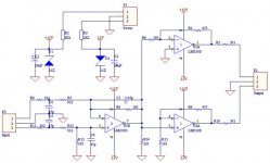
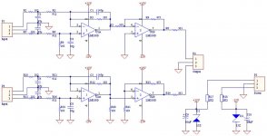
for TA3020 amplifier and not only, to prevent the supply rails to experience bus-pumping phenomenon, one simple sollution is to drive the L and R channels with 180* shifted audio signal. one of the loudspeakers, from the channel which use inverted signal must be inverted the polarity too. another advantage is that the amplifier can beused directly in BTL mode.
i will attach 2 schematics, one for mono, balanced input, which drives both channels in BTL mode, and one for stereo, also balanced input. if you don't want to use balanced input, just connect the inverting input to GND and use only the non-inverting one. the gain of this stage is given by the resistor between output and inverted input of the op-amp and the res. to gnd. easy to calculate, i don't insist on this aspect. for best performance, the OP amp must be low-noise one, NE5532 or OPA....
for mono BTL, and balanced input, the cheapest and most siplest sollution is to drive the amp directely, one channel with inverted signal. one with non-inverted.
Attachments
- Status
- Not open for further replies.
- Home
- Vendor's Bazaar
- NEW Audio amplifier kits, modules and many others.