ULD Extreme
Andrew
If you are going with 330uF, don't use a Wima 10uF MKS2 for convenience. They sound terrible as input caps, far worse than the 4.7uF Wima MKS2. They must have done something different to make them so compact ? I'm giving mine away to another diyAudio member.
Alex
Andrew
If you are going with 330uF, don't use a Wima 10uF MKS2 for convenience. They sound terrible as input caps, far worse than the 4.7uF Wima MKS2. They must have done something different to make them so compact ? I'm giving mine away to another diyAudio member.
Alex
I already have 10off 10uF film and foil polypropylene that I use at the output of pre-amps and input of power amps. They're monsters.
I never expect anyone to design their PCB to suit my weird requirements.
I try to advise to meet many more sensible requirements.
I never expect anyone to design their PCB to suit my weird requirements.
I try to advise to meet many more sensible requirements.
The basic problem is that 47uF is wrong in combination with 220uF.Carl_Huff said:Somebody suggest a good part to use for the 47uF non polar cap at the signal in position.
The ratio between these caps must be changed to prevent AC voltage across the NFB cap, otherwise avoidable distortion is introduced.
Andrew, Carl,
While discussing the input capacitors you have hit on a point concerning physical size -- "its a monster". In many instances two caps of the identical specs have greatly different physical dimensions. Has anyone every shown that the added area, in a film cap for example, contributes anything to the quality of the device. My only A to B comparison experience is with the sound of small SMD caps. They seem to sound very bright. I discovered this while constructing the first BPA300 chip amp.
Are boards going to be available for the amplifier?
Tad
Andrew, Alex & Hugh,
Let's come together on a concensus as to what the input network and feed back cap amounts to. When we are done we need to have vendors and part numbers for the described parts. I suggest that 'DC in' amounts to a jumpers in place of the 47uF cap and the 12K resistor. Is that acceptable?
And are your favorite bypass caps for hanging off of the output collectors to ground? Suggestions? Thoughts?
Tad,
When we are done it is my intention to post the project files (Sprint Layout for PBCs and SPlan for Schematics) as well as the gerbers for all that want them. However I would think that someone should build and test a prototype from those files before there is a group buy.
When we are done it is my intention to post the project files (Sprint Layout for PBCs and SPlan for Schematics) as well as the gerbers for all that want them. However I would think that someone should build and test a prototype from those files before there is a group buy.
A suggestion ...
Change the input cap that is now shown as 47uF be changed to a 4.7uF Wima MKS2 device. That fixes the input hi-pass to be 3dB down at 3Hz.
In the case of the cap in the feedback position, what if we specify it as a Nichicon MUSE? The 16 volt 220uF, 330uf and 470uf caps all have a 5mm pinout. The device diameter changes from 10mm to 12.5mm. I would simply plan for the larger diameter for those parties that want a larger cap in the feedback position.
Anyone have a preference for cap type for the 820pF device? Should it be box ceramic or silver mica?
Thoughts anyone?
Carl_Huff said:A suggestion ...
Change the input cap that is now shown as 47uF be changed to a 4.7uF Wima MKS2 device. That fixes the input hi-pass to be 3dB down at 3Hz.
In the case of the cap in the feedback position, what if we specify it as a Nichicon MUSE? The 16 volt 220uF, 330uf and 470uf caps all have a 5mm pinout. The device diameter changes from 10mm to 12.5mm. I would simply plan for the larger diameter for those parties that want a larger cap in the feedback position.
Anyone have a preference for cap type for the 820pF device? Should it be box ceramic or silver mica?
Thoughts anyone?
Hi Carl, the original article explains why they used the components they did. Probably a good place to start.
"Some readers may wonder why we used such large electrolytic in the input and feedback networks. The answer is that we are acting to eliminate the effects of capacitor distortion in the audio passband ..... (and) to minimise the source impedance seen by the input transistors." (SC Aug 2008 )
Another 2 paras explain further in some detail.
Terry
Carl_Huff said:A suggestion ...
Anyone have a preference for cap type for the 820pF device? Should it be box ceramic or silver mica?
Thoughts anyone?
I use and advocate polystyrene.
it's not the size (value) that is the problem. I agree fully on the low impedance advantages.pheonix358 said:"Some readers may wonder why we used such large electrolytic in the input and feedback networks. The answer is that we are acting to eliminate the effects of capacitor distortion in the audio passband ..... (and) to minimise the source impedance seen by the input transistors." (SC Aug 2008 )
The problem is the ratio between them.
Cin<= Rfb / Rin * Cfb / 1.4
Cin = 47uF is NOT LESS than 6.6uF.
The ratio must be sorted. Then you can play with values while maintaining the required ratio.
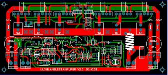
That layout is rather nice Carl. What is the value of the output resistor in the wire coil? The green earth people will like this. Very little wasted copper on this pcb. Will the resistor pad holes except the FAT Dale RN resistor leads? Just a small problem I had in the past.
Tad
Tad
Tad,
The resistor that you refer to is specified to be 6.8 ohms at 1 watt. The schematic is posted back on post #167. The library part that I used in the layout is for a Vishay/Dale CW 3 watt part. The Mouser part number is 71-CW2B-7.5. The PCB thru holes are .047 inches (1.2mm) and are spaced 1 inch (25.4mm) apart. Similar parts equivalent to the one specified should work equally as well.
The resistor that you refer to is specified to be 6.8 ohms at 1 watt. The schematic is posted back on post #167. The library part that I used in the layout is for a Vishay/Dale CW 3 watt part. The Mouser part number is 71-CW2B-7.5. The PCB thru holes are .047 inches (1.2mm) and are spaced 1 inch (25.4mm) apart. Similar parts equivalent to the one specified should work equally as well.
I have the PCB layout in Sprint Layout form ready for review. I need one or more parties to compare the PCB to the schematic to be sure that they match! There is a free viewer on the Sprint Layout site.
Is anyone reading this willing to host the files for those that want to download them?
Is anyone reading this willing to host the files for those that want to download them?
It has been rather quiet around here and no one has stepped forward to host the project files. Is there interest by anyone here to build this revised amplifier?
Carl_Huff said:It has been rather quiet around here and no one has stepped forward to host the project files. Is there interest by anyone here to build this revised amplifier?
Hi Carl, I would if I could but at the internet speeds we have in country AUstralia I don't think I can. As for building these babies, yes, definately. About 8 I think.
Terry
Terry,
Before any of us spend the money to spin PCBs for a build, I need someone to check the PCB layout against the schematic to be sure that I haven't made a mistake. Would you be up for the task? I plan to check it again myself.
There is a free viewer on the Sprint Layout website. Sprint Layout viewer
Before any of us spend the money to spin PCBs for a build, I need someone to check the PCB layout against the schematic to be sure that I haven't made a mistake. Would you be up for the task? I plan to check it again myself.
There is a free viewer on the Sprint Layout website. Sprint Layout viewer
Carl_Huff said:Terry,
Before any of us spend the money to spin PCBs for a build, I need someone to check the PCB layout against the schematic to be sure that I haven't made a mistake. Would you be up for the task? I plan to check it again myself.
There is a free viewer on the Sprint Layout website. Sprint Layout viewer
No problems, I have never tried this with a double sided card b4 but can't be that hard.
Terry
Carl_Huff said:Terry,
Before any of us spend the money to spin PCBs for a build, I need someone to check the PCB layout against the schematic to be sure that I haven't made a mistake. Would you be up for the task? I plan to check it again myself.
There is a free viewer on the Sprint Layout website. Sprint Layout viewer
I have the viewer, now what?
- Status
- Not open for further replies.
- Home
- Amplifiers
- Solid State
- New Amplifier - ULD Extreme