Hi there
I hope no one mentions an Oscilloscope. It's the one bit of kit I have wanted for ages and the one I still don't have!
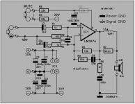
OK here are the schematics and current PCB patterns. First is the Amplifier.
The capacitor on the left, in blue, is an on the fly correction. As I had it positioned incorrectly initially. On the schematic R8 is shown, ghosted, in the position I ended up with on the PCB due to oversite.
For now I have removed R8 from the PCB, replacing it with a wire link, and have fitted it to the mute switch to get this correct. The PCB fully matches the schematic at this point.
The only other change to the original design, other than the changes suggested by Andrew, is the Capacitor C1. This was shown as a 2u2 'ceramic'. I fitted an electrolytic cap of 2u2.
Everything appears correct. Soldering is all good and no bridges/shorts anywhere. I have checked the VDC at the Amplifier and +/-30VDC is present and correct.
My audio source was an Archos 1.8c Vision MP3 type player. Set to mute on volume and slowly turned up.
A quick retest and I still get the cone fully deflecting inwards with or without a source attached.
regards
Foo.. Stillslightlyunhappybuthopeful.
I hope no one mentions an Oscilloscope. It's the one bit of kit I have wanted for ages and the one I still don't have!
OK here are the schematics and current PCB patterns. First is the Amplifier.
The capacitor on the left, in blue, is an on the fly correction. As I had it positioned incorrectly initially. On the schematic R8 is shown, ghosted, in the position I ended up with on the PCB due to oversite.
For now I have removed R8 from the PCB, replacing it with a wire link, and have fitted it to the mute switch to get this correct. The PCB fully matches the schematic at this point.
The only other change to the original design, other than the changes suggested by Andrew, is the Capacitor C1. This was shown as a 2u2 'ceramic'. I fitted an electrolytic cap of 2u2.
Everything appears correct. Soldering is all good and no bridges/shorts anywhere. I have checked the VDC at the Amplifier and +/-30VDC is present and correct.
My audio source was an Archos 1.8c Vision MP3 type player. Set to mute on volume and slowly turned up.
A quick retest and I still get the cone fully deflecting inwards with or without a source attached.
regards
Foo.. Stillslightlyunhappybuthopeful.
Attachments

the link could be interesting reading if we could rely on the credentials of the responders to the student's questions.
Some of it reads like the "blind leading the blind".
Hello Andrew
I'm afraid I did. very foolish I know and I may well be paying the price now of course.
I have the second amp which has not been connected of course. Small consolation perhaps and lesson learned.
regards
Foo
I'm afraid I did. very foolish I know and I may well be paying the price now of course.
I have the second amp which has not been connected of course. Small consolation perhaps and lesson learned.
regards
Foo
the link could be interesting reading if we could rely on the credentials of the responders to the student's questions.
Some of it reads like the "blind leading the blind".
It's not that great, I just wanted to offer him something more then, "my cheap multimeter still reads AC on a DC power supply"
Hi there
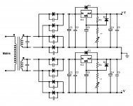
At the rectifiers I am getting 42.3VDC. This is correct as far as the maths go.
Fingers crossed I can, with help, get this going. I have already redone the PCB design to allow easier fitting of the chip to a heat sink and with the 'corrections' done.
Looking at the current design I could, with a single wire bridge, make the circuit as per it's original set up where the audio in GND was connected to the power GND. Purelt to see if this makes a difference to it's function.
regards
Foo
If you connect caps of about 470uF to the output of the regulator boards, what DC voltage do you get at the 470uF caps?
In this case, all of the output will be DC; however, if your V+ really does output way too much voltage, a capacitor may explode, so do consider wearing eye protection.
In this case, all of the output will be DC; however, if your V+ really does output way too much voltage, a capacitor may explode, so do consider wearing eye protection.
Hello there
I had a 330uF@40V cap handy and a pair of goggles 😀
Wired it up, powered it up and I get 30VDC on the positive rail and the negative rail. No pops, bangs or fireworks.
So far so good
regards
Foo
I had a 330uF@40V cap handy and a pair of goggles 😀
Wired it up, powered it up and I get 30VDC on the positive rail and the negative rail. No pops, bangs or fireworks.
So far so good
regards
Foo
Looking at the current design I could, with a single wire bridge, make the circuit as per it's original set up where the audio in GND was connected to the power GND.
At the amplifier board, audio ground can connect to power ground via 10R, 8R2, 6R8, 5R6, 4R7, 3R9, 2R7, 2R2, 1R8, 1R5, 1R2, 1R, or solid wire. Although larger size boards may use a long/thin trace, it is normal to use a resistor in compact builds.
However, disconnect would make crazy offset and/or unexpected operation.
Hello there
Ah. I have seen this sort of thing mentioned here and there on the forum. Connecting the audio GND with a resistor to star ground? or chassis GND. I'll give it a try and see what occurs.
regards
Foo
Ah. I have seen this sort of thing mentioned here and there on the forum. Connecting the audio GND with a resistor to star ground? or chassis GND. I'll give it a try and see what occurs.
regards
Foo
Hello there
Ah. I have seen this sort of thing mentioned here and there on the forum. Connecting the audio GND with a resistor to star ground? or chassis GND. I'll give it a try and see what occurs.
regards
Foo
Your amplifier board schematic shows one pair of 1000uF caps. The 0v centerpoint between these two caps is the spot you're looking for.
In that test, if same dial settings, same result on both regulated rails means same amount of AC on both regulated rails, which seems to be zero.At the rectifiers I am getting 42.3VDC.
. . .
Wired it up, powered it up and I get 30VDC on the positive rail and the negative rail.
Okay, please remember to drain the test cap safely. A 30R 5W (or really anything similar) with insulated wire leads and insulated gator clips makes a nice cap drainer. And, be careful.
After you get a working audio ground and thus no more offset, I think your next question will be why the regulators are so hot. Well, let's try to count up necessary voltage drop, only what is required to hold the rails steady, and then dial in 35v for both rails. That figure is a guess, but reasonable. We can fine tune it later.
Don't forget to heatsink both the audio amp and regulators. Check amplifier output with DC voltmeter before connecting speaker.
Last edited:
Hello there
WOOOOOOOOOHOOOOOOOOOOOOO! Etc, etc!
I am pleased to report that amplifier is working... Perfectly. Adele's dulcet tones are emenating from the speaker as we speak.
Regulator is warm but I can keep my hand on the sink no problem. The speaker I have is 4Ohm, used because the big speaker is stuffed of course, and is rated for 30W. But I am not pushing the unit until I have both set up and have built my needles with the 8Ohm visitron's.
SO the question here is. When it comes to setting up proper what should I be doing with the 10R resistor?
Currently the +VE, -VE , and GND link directly from the regulator to the amplifier. Should the GND be taken to chassis, if I make a metal enclosure, from both directions and then link out the additional resistor to the same point?
The speaker I am using is uncased, it's all I had to hand, but the overall impression of the output is very good, clarity, good bass, better than I have heard in a long time. It can only get better with the proper speakers!!
Jobs to do now are - Make the strap to hold amplifier two onto it's sink. Prep the second regulator sink for fitting and make a proper test bed to secure everything in place.
I haven't felt this excited since I first stepped back into the hobby 😀
DC on the output, before I forget, 3.3mV. Without a source plugged in you can hear a faint 'noise' but with the source nothing.
Have I said how excited I am? ROFLMAO!
Thanks everyone for your guidance, advice and patience. I will also be pressing ahead with version 2 PCB as well which is a much kinder layout and I think looks much better.
regards
Foo.. Eversuchalothappierjustincaseyouhadn'tnoticed
Attachments

First test, the NFB cap, C3, 22u, seems too small.
You can take your spare 330u test cap and drain it again (0v, no charge) and then solder it trackside, in parallel with that 22u nfb cap. The combined value of 352u is surely big enough. See if you get a lot more low clear bass.
EDIT:
The 30v rails are fine for use with 4 ohm speaker--slightly warm regs are better than really hot amp.
EDIT2:
However, unless you have a preamp, the gain of 19 (shown by the schematic) might be a bit too small for use with computer and ipod. Gain increases the influence of the amp, so the low gain plus a preamp might be worth a try with any spike system chip amp (aka, not increasing your power amp gain). Decibel Dungeon has that NE5532 project and discussion, and you could give it a gain of 6 to 8 or so.
Last edited:
Hello there
I will have a bash with the extra cap tomorrow. It's late here and I hear my bed calling me 😀
regards
Foo
I will have a bash with the extra cap tomorrow. It's late here and I hear my bed calling me 😀
regards
Foo
Hello there
Yep that's the one.
I have had to drag myself off of this current excitement to finish up some voice mod kits that have been pending for far to long. So I shall clear these up, three kits, and one build and then get back on the case.
A lucky find incidently, in the shed, a pair of RCA terminated speaker cables. The wires are single core, shielded and are about 8mm in diameter.
I also have just about enough parts to build one more amp board, of the new layout. I also purchased, with my last order 2 pairs of silver mica caps for the next version. I may well be being keen here you know 😀
regards
Foo
Hello there
I've done the bulk of my 'other jobs' so have returned to my 1/2 complete amp. Currently it is strung out on the arm of the sofa playing any random tune I select. 😀
PSU and Rectifier 2 have had their pins and interconnects soldered in place and I just have to cut, drill, and fit the Regulator Sink. Amplifier 2 sink is marked up and just needs drilling for the strap that will hold the chip in place.
Back to the working unit - At this juncture I wont play with any component values. I need to get familiar with it's current output before I enter the realms of 'tweaking' by ear.
That said, even with a mere bare speaker cone of unknown parentage, I can hear the quality I will be getting once I have built my own speakers. Well defined vocals, great percussion and acoustics.
I have done one tweak. I have turned the regulator up to +/- 35VDC. Why not. It's there so I may as well use it.
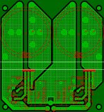
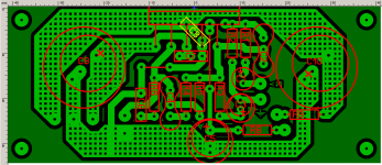
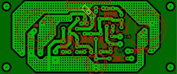
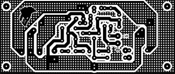
See also the attached images of the refined and improved layout of the Amplifier.
Carry on soldering!
regards
Foo
I've done the bulk of my 'other jobs' so have returned to my 1/2 complete amp. Currently it is strung out on the arm of the sofa playing any random tune I select. 😀
PSU and Rectifier 2 have had their pins and interconnects soldered in place and I just have to cut, drill, and fit the Regulator Sink. Amplifier 2 sink is marked up and just needs drilling for the strap that will hold the chip in place.
Back to the working unit - At this juncture I wont play with any component values. I need to get familiar with it's current output before I enter the realms of 'tweaking' by ear.
That said, even with a mere bare speaker cone of unknown parentage, I can hear the quality I will be getting once I have built my own speakers. Well defined vocals, great percussion and acoustics.
I have done one tweak. I have turned the regulator up to +/- 35VDC. Why not. It's there so I may as well use it.
See also the attached images of the refined and improved layout of the Amplifier.
Carry on soldering!
regards
Foo
Attachments
- Status
- Not open for further replies.
- Home
- Amplifiers
- Chip Amps
- New amplifier...possibly..