Hello there
The second PCB is now complete. Heat sinks should be with me tomorrow by the looks of it. So I had better prepare a test block to bolt everything down for testing.
I'll also have to dig out my old hi-fi speakers and see if they will do for 'testing'. Failing that I could knock up the headphone circuit to use for initial tests.
So far this has been a very fulfilling project. Fingers crossed it continues to progress positively.
Also on the shopping list is wire, power sockets, RCA, and speaker posts. A lot of the power wire will probably come from some dead PC PSU's I have kept for such eventualities...Actually it occurs to me that the IEC sockets from the same will come in very useful!
regards
Foo
Hello all
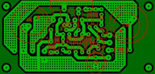
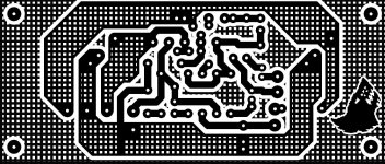
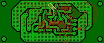
During the lull, waiting for further parts, I have played with the layout of the PCB a bit.
All resistors are now horizontal. Most of the capacitor mount points now have multiple pitch capacity.
The board is now 73mm X 35mm. Fingers crossed I have kept the audio paths short enough.
regards
Foo
During the lull, waiting for further parts, I have played with the layout of the PCB a bit.
All resistors are now horizontal. Most of the capacitor mount points now have multiple pitch capacity.
The board is now 73mm X 35mm. Fingers crossed I have kept the audio paths short enough.
regards
Foo
Attachments
Hello there
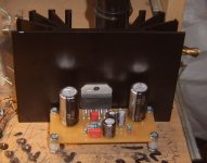
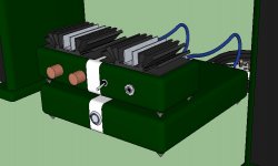
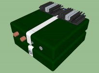
Heat sinks arrived today 😀
Dry fitting indicates my PCB needs a bit shaving off the rear edge, where the LM3876T is, to allow the same to sit, without help, flat on the sink.
It is only raised by a round 0.5mm but lets get it right!
I think I will be looking at using a 'bar' to strap the IC's in place rather than relying on the top hat and bolt purely because of the size of the IC.
I've never had an issue with TDA2003 IC's, which I use a lot, with just the top hat and bolt but then they are narrower.
Right I'm off to the attic to grab a defunct PC PSU for 'sacrificial duties' 😱
regards
Foo
Attachments
Hello there
Gutting the PC PSU has been very productive!
Apart from the wire It has also given up a power socket, molex headers and a pair of extruded heat sinks that will do very nicely for the regulators 😀
A couple of dead PC DVD ROMS have been annihilated to get to the molex sockets which themselves have been destroyed to release the metal pins.
These have been soldered onto the regulator output. The molex plugs have been broken down so I have 3 pairs of wires per regulator that plug onto the boards.
On the amplifiers 3 1.5mm pins have been fitted as the power in points. From the same PSU the main power molex power plug has matching female pins to plug onto the Amplifier pins. So a bit of neat splicing, judicious use of heat shrink and I'll have a nice set of power leads for the internal hook ups.
I have other defunct PSU's and ROM drives which I will rob to make the connects between the rectifier boards and regulators. It's all good!
regards
Foo
Attachments
In the photo above, regulators don't really require such large caps at input side, can't use such large caps at output side, and the heatsink will cook them because of insufficient clearance. You might want to swap those for some 2200uF to 4700uF size and save those big 10,000uF caps for a project that has unregulated power. Also the power pins are too close together and need some sheath installed or simply weave and glue a kapton scrap between them or anything safer than that photo.
Well, its all really close, but could be refined a bit for thermal handling and for electrical insulation.
P.S.
On the photo before this, you can hold the board down firmly to a flat surface, grab the chip and tilt it away from the board, and after that, you can straighten it flush with the heatsink. Those pins have tolerance to bend twice and that is twice. You can correct easily 1mm, so your 0.5mm is no problem. I'd rather do it in dry fit; however, stabilizing your soldering by applying pressure on the bottom of the board (to the chip pins), allows one to do it at any time. After that, and after thermal insulation, you can then secure the board and it helps press the chip against the heatsink.
Conversely, if using a clamp bar, that is strong enough to put the chip right into place without having to bend anything beforehand--the clamping will easily correct that 0.5mm. However, you will want to slightly smooth the sharp edges of the chip with some black sandpaper so that sharp edges don't exist to cut through the silicon pad.
Hello there
The regulator is based on the Dungeon Dimension set up. Admittedly the large input caps on NUUK's were fitted in a more heat friendly way. I will slip a baffle in to rebuff the heat.
The power headers will be insulated. This is already planned so fear not!
I'll be taking it very careful with the IC/heat sink fitting. It would be a shame to stuff it up this close to finishing!
regards
Foo
At the regulator board, you could reduce/eliminate heat pooling by drilling a couple of holes to allow cool air to go through at the heatsink area. That's just because cool air intakes are helpful to heatsinks of all sizes. 🙂 Maybe a bit of unobtrusive ventilation could prevent hot air from getting trapped between the big caps and heatsink.
Hello there
There will be a slot opened up around the top of the heat sink and underneath there will be plenty of holes to help the circulation.
regards
Foo
There will be a slot opened up around the top of the heat sink and underneath there will be plenty of holes to help the circulation.
regards
Foo
Hello there
I have to get some heat shrink tubing to assemble and make safe the interconnects for the Amp so there is a slight pause in progress. I also have to fit the heat sinks as well of course.
In the meantime here are the latest images of the art work for the amplifier PCB. C8 which fits under the PCB now has it's own solder pads to make for a neater fitting. The PCB is now 82mm Wide purely to match the rectifier and regulator PCB. Symmetry??
Any hoo Enjoy!
regards
Foo
Attachments
Hello there
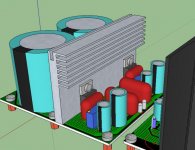
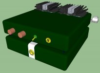
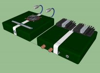
I have also, hopefully, settled on an enclosure design as well. Two enclosures. One for the amplifiers and one for the power supply. In the end it just seemed easier to make a nice looking set up by not trying to have everything in one enclosure.
I know it's not impossible but I just couldn't settle on a lay out topology. I am also trying to follow the lines of the 'proposed' Cyburg's Needles I intend to build.
Heat shrink and braided sleeving are to be ordered on ebay tomorrow!
Regards
Foo
PS. I know the heat sinks are horizontal and this may not be the best for cooling efficiency but I'm game!
Attachments
There's two ways to work your heatsinks that way:
1). Hopefully that box is metal and so no problem at all with your heatsink size after the box increases it.
2). If the box isn't metal, you can use hottop configuration whereby you set the heatsinks up on washers and allow air from the air intake at the bottom of the box to go up and around the heatsink on the way out of vents located directly underneath the heatsink (creating a draft). In this case, it may also be necessary to add more metal to the bottom/back side of the heatsink, since a slick surface isn't great at air thermal conduction.
Power config:
No matter if using regulators or not, that enclosure configuration is especially suited to CRC, but in this case, the "R" in CRC is the interconnect cable between the two enclosures. This means that either large caps, capmulti or regulators goes in the amplifier enclosure. If also handling the heat from regulators, that enclosure is too small.
P.S.
You made the U-channel mod look very attractive. Kudos!
Hello there
Progress is slow 😀 I have lots of wire, heat shrink and braided sheath to do the wiring.
The enclosure, amp section, IS too small. But mainly because it occured to me that I have plans to fit a speaker protection circuit, RIAA Circuit and dedicated ear phone circuit. I will be fitting the 'simple version' you showed me for the near future though. So I need a larger amp enclosure for this future expansion.
For uniformity and less hassle I think making the power block and amp section the same size Is the way to go. This instantly shortens the interconnect power leads and makes the unit look a lot more unified.
regards
Foo
Attachments
I liked your heatsinks on front so the small signal wouldn't have to make two trips, and it looked attractive too.
I think the power switch goes on the power box so you wouldn't have mains next to small signal.
Except for ventilation difficulty, I can't see why you couldn't use 2 of the smaller boxes like:
2 amp boards and their associated reg boards in the top box.
1 power switch, 1 toroid, 2 rectifiers, 2 caps, in the bottom box.
Other than that, full monobloc build makes sense because it would be easier to cool given that 1 amp board, 1 reg board to 1 box is the same as half as much heat per each oven. It is something to consider.
P.S.
If the boxes are metal, mount the heatsinks to the boxes with some thermal paste and that will make the heatsinks get really big as long as the box is ventilated nicely.
Hi there
I liked the small amp form to. But to accomodate the future additions this is the best answer. The volume pot will be mounted at the back near the input/amplifiers and an extension rod used to link up to the outside world. This will keep the audio wiring as short as possible.
The large toggle switch on the amp box is actually for switching from speaker to headphone. The power switch is a push to make momentary contact switch. This will be connected to an LM555 bistable circuit which will drive a relay. The circuit will act as a toggle switch - Push one for on push again for off. I may make a duplicate to act as the main speaker/headphone control.
In other news -
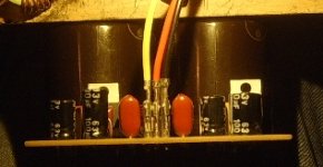
One transformer, One rectifier, and one regulator were wired together today and powered up. First readings were +34.9VDC and -35.3VDC. Two minutes with a small screwdriver on the trim pots and 'Presto Chango!" +/-30VDC was achieved. The setup was left for an hour and checked every ten minutes or so and the voltage has remained stable and the heat sink remained at 'room temperature'. Obviouisly the PSU is unloaded at this point and may require tweaking once working under load. But it's all good!
regards
Foo
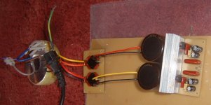
I liked the small amp form to. But to accomodate the future additions this is the best answer. The volume pot will be mounted at the back near the input/amplifiers and an extension rod used to link up to the outside world. This will keep the audio wiring as short as possible.
The large toggle switch on the amp box is actually for switching from speaker to headphone. The power switch is a push to make momentary contact switch. This will be connected to an LM555 bistable circuit which will drive a relay. The circuit will act as a toggle switch - Push one for on push again for off. I may make a duplicate to act as the main speaker/headphone control.
In other news -
One transformer, One rectifier, and one regulator were wired together today and powered up. First readings were +34.9VDC and -35.3VDC. Two minutes with a small screwdriver on the trim pots and 'Presto Chango!" +/-30VDC was achieved. The setup was left for an hour and checked every ten minutes or so and the voltage has remained stable and the heat sink remained at 'room temperature'. Obviouisly the PSU is unloaded at this point and may require tweaking once working under load. But it's all good!
regards
Foo
Attachments

On the power circuit that I see pictured there, you need to put 1,000uF or 2,200uF 50v skinny type caps right where you've got the cables on your rectifier boards, and then simply attach the cables to the cap pins.
The 10kuF caps at the regulator board are needlessly slow to charge. Those should be 2,200uF or 3,300uF. Snap cap will fit perfectly or you could simply add one drilling and then normal caps fit. Save the 10kuF for your next unregulated supply.
Anyway, what I've outlined is ~2,200uF. . . interlink cable. . . ~2,200uF. That is a sort of CRC and very fast.
It appears that regulator boards are in the wrong box. Regulator to audio amp interlink cable needs to be 1cm or less; otherwise some of the benefit is lost.
Thermal:
Your amplifier enclosure needs air intake at front bottom, air output at rear top; however, your power enclosure needs air intake at rear bottom, air output at front top, and this is because you don't want to put the heat from the power box into the amp box. Edit: Your arrangement there is very close, but you don't need that fan grille opening.
Last edited:
Oh dear
Somethings not right..
I have ploughed a head and got one amp mounted to it's sink and set up for a quick test run.
This was done, unwisely I know, without a lamp tester in situ. Forst up it seems my speakers have not weathered the storage to well as the rubber rim has fallen to pieces 🙁
Second up the cone sucks all the way in and I can only just hear music at the mid cone. Measuring the output at the amp I get a reading of 61VAC. I am on the 200V scale.
Ho Hum..............
Foo
The only error I have found on the board is the mute line.
Currently it runs Pin8 --[ R8 ]-- C5 +VE - mute pad.
It should run Pin8 - C5 +VE --[ R8 ]-- mute pad.
Not sure if this swapped order would cause the issue in hand though. The mute function does work it seems.
regards
Foo
Currently it runs Pin8 --[ R8 ]-- C5 +VE - mute pad.
It should run Pin8 - C5 +VE --[ R8 ]-- mute pad.
Not sure if this swapped order would cause the issue in hand though. The mute function does work it seems.
regards
Foo
Amp output is 61v of noise? I'm not familiar with that particular problem (except for dubstep, would, of course, cause 61v of noise). How much AC comes from the regulator boards? And, what is your amplifier input load? How much DC offset at amp output?
Can you reverse engineer your schematic, reading it off from your amp board and then post it?
During testing with speaker, install a large cap series to the speaker--I think that any workbench test speaker should be DC protected that way.
P.S.
You need to buy some new rubber surrounds and suitable glue for those woofers. If the woofer cone has a formed flat edge then get a flat edge surround or if the woofer cone has a natural (normal cone shape) bevel edge then get a bevel edge surround. The risk is low, the price is low and replacement surrounds work better than either duct tape or omission. 🙂
Last edited:
Hello there
I'm working back through the PCB and schematic and all seems well other than the mute Cap and resistor as mentioned earlier. I will post the PCB and schematic once done.
I have found the source of the 61VAC noise.
I checked the regulator circuit. It has +/-30VDC as required. But when I check it with the DMM set to AC I am getting 61VAC on the Positive rail............. Thinking this may be a fault of this unit I wired up the second unit. Same result 61VAC on the positive rail.
I'm rechecking the schematic and the PCB's but thus far I can't see anything wrong.
Regards
Foo.. The eversoslightlynothappy.
Multimeter AC and DC Misuse
Measuring DC on AC and vice versa is inaccurate. You will have to find another way to check. Feel eversoslightly better. lol
Measuring DC on AC and vice versa is inaccurate. You will have to find another way to check. Feel eversoslightly better. lol
- Status
- Not open for further replies.
- Home
- Amplifiers
- Chip Amps
- New amplifier...possibly..