A slight brain wave!
Go to a site and input the Thermal rating Length, width and height and see what comes up.
Now I have been reading so much I seem to have addled my brain. So for a single IC is a Heat sink with a Thermal Rating of 2.2C/W better than one with a rating of 1.1C/W? If I still have a grasp I think the 2.2C/W because it will 'shift' more C per Watt of the source.
Regards
Foo
C/W is the rating of how high the temperature of the sink rises above ambient when power is dissipated.
A 2.2C/W sink when dissipating 1W will rise to Ta+2.2Cdegrees.
But, the rating of the sink is usually determined when the Ts at the interface is 70Cdegrees to 75Cdegrees above Ta.
For Ts-Ta><70Cdegrees, a correction factor must be applied to bring the model closer to reality.
eg. ask that same 2.2C/W sink to dissipate 30W. Ts-Ta ~ 2.2 * 30 = 60Cdegrees.
That is pretty close to the 70Cdegree so I'll leave it as is, the Derating Factor (DF) is assumed to be 1.0
Now ask the sink to dissipate half that power, 15W. The model says Ts-Ta ~ 33Cdegrees. That is far away from 70Cdegrees so we apply a DF to suit the lower temperature rise. Let's guess at 1.2
The sink Manufacturers usually give you DF or sufficient data to derive DF.
The corrected model now predicts temperature rise, Ts-Ta ~ 2.2 * 15 *1.2 = 39.6Cdegrees.
If Ta = 21degC then Ts ~ 60.6degC.
Last edited:
How much metal stuff will you be able to bolt onto the heatsink that you already bought? Square channel, angle, and u-channel, if large size, are all dramatically effective to boost heatsink size.
Hi there
Thanks for the reference Andrew. It clears the mire a tad. I shall have to try again!
Daniel - I think 'Non at all' Covers that =D
I'm quite happy to purchase more heat sinks.
Black anodised 50mm X 97mm X 25mmHigh with a TR of 2.3C/W 2off is currently in my sights. See link
Sinks
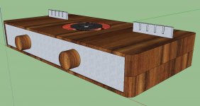
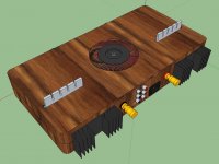
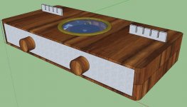
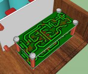
See Also the images of my current thoughts on set up.
regards
Foo
Thanks for the reference Andrew. It clears the mire a tad. I shall have to try again!
Daniel - I think 'Non at all' Covers that =D
I'm quite happy to purchase more heat sinks.
Black anodised 50mm X 97mm X 25mmHigh with a TR of 2.3C/W 2off is currently in my sights. See link
Sinks
See Also the images of my current thoughts on set up.
regards
Foo
Attachments
Heatsink? Even worse? I have those heatsinks. My parallel LM1875 overwhelmed one of them. Those heatsinks are a bit small. RS seems to double prices to make their produce look important, but most of their heatsinks are both small and expensive. Wow.
P.S.
Top of that enclosure looks hazardous. Transformer wire coating is not a guarantee--it is frail. Is that a window or is it a shock?
P.S.
Top of that enclosure looks hazardous. Transformer wire coating is not a guarantee--it is frail. Is that a window or is it a shock?
Last edited:
Hello there
Hmm. It's a bit of a mystic area this bleedin' heat sink lark! I will review!
WIP A window and bezel will be fitted to prevent any 'issues' in the future. The regulator heat sinks will be insulated from the LM388's and an earthed cage type surround fitted 'just in case'.
regards
Foo
Hmm. It's a bit of a mystic area this bleedin' heat sink lark! I will review!
WIP A window and bezel will be fitted to prevent any 'issues' in the future. The regulator heat sinks will be insulated from the LM388's and an earthed cage type surround fitted 'just in case'.
regards
Foo
Attachments
Hi Daniel
I concur. Aids the internal air flow wouldn't it. Well at least be a vent for hot air rising. Perhaps something in brass. Filigree worked.....
Here's a larger sink. 120 x 75 x 37mm @ 1.3C/W.
Sinking fast
Tell me it'll do pleeeeeeeeeease!
regards
Foo
I concur. Aids the internal air flow wouldn't it. Well at least be a vent for hot air rising. Perhaps something in brass. Filigree worked.....
Here's a larger sink. 120 x 75 x 37mm @ 1.3C/W.
Sinking fast
Tell me it'll do pleeeeeeeeeease!
regards
Foo
What's the airflow like through the heatsink?
That determines what value you guess for Ta.
Then look up the National chart and double the size they tell you, i.e. half the Rth s-a value.
That determines what value you guess for Ta.
Then look up the National chart and double the size they tell you, i.e. half the Rth s-a value.
Two of those per each chip (4 total) should be adequate and there might be some effort splicing them together by adding to the backplate.
These will work better (1 per each chip):
Inordinately overpriced normal size heatsink from RS #1
Inordinately overpriced normal size heatsink from RS #2
These will work better (1 per each chip):
Inordinately overpriced normal size heatsink from RS #1
Inordinately overpriced normal size heatsink from RS #2

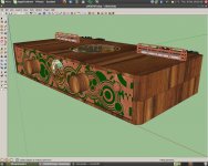
I fear there is some steam punk influence occurring :O
By all means, let's see a wild Steam Punk Noveau amp chassis. 😀
Some thing like this -
See also a headphone amp, possibility.
regards
Foo
See also a headphone amp, possibility.
regards
Foo
Attachments
Last edited:
Those heatsinks last shown will support a square tube or u-channel in center to boost their effective size. I actually re-cycle square tube (plus paste) bits from old TV antennas just for these "gap in the middle" heatsinks, because, otherwise, that slick wall bit in the middle just sits there doing no work. Drilling a few extra holes in the square tube (makes for easier mounting anyway) disturbs the airflow and increases the effectiveness.
Added metal also works on the inside, above the amplifier, if you have adequate ventilation. In this case, air intake underneath the amplifier board, briskly sails up the slick wall of the heatsink doing absolutely nothing useful until it encounters my added angle channel "shelf" that it has to go around and in doing so takes the heat out with it.
You can also mount heatsink to additional metal, such as if the side of the amplifier were metal, a right angle channel (hidden on the inside) could conduct the heat from the back to the side. Now, that would be strongly effective. Commercial amplifiers almost always use some scheme with the chassis mounting brackets to make the heatsink effectively much larger.
P.S.
Don't forget to put some air holes underneath the amplifier board so that we don't boil the capacitors.
Headphone Adaptor for Power AmplifiersSee also a headphone amp, possibility.
Known good headphones are a more reliable than speakers for judging and fine tuning audio amplifiers. Of course you should have many more tools than that. However, I would consider a headphone jack as a necessity.
P.S.
On the topic of tone, I'm sure that you will want to locate the regulator/capmulti boards as near as possible to the amplifier boards whenever using spike system chips. That placement will possibly help keep the baritone fresh, loud and clear which might help achieve a flatter frequency response. I would also use very thick solid copper cable (of extremely short length) between regulator/capmulti board to amplifier board.
Hello there
I will bare the heat sink 'extensions' in mind. I'm sure I can lay my hands on some when needed.
I will review additional venting once I have got as far as building my enclosure but I will have 'under board' vents to allow the flow of air.
Headphones - Now that's a natty little circuit to add. Nice, simple and immediate. The circuit I have been looking at uses 'cross feed'. I am intrigued by the idea.. But it is a project for later, once the main build is done.
At the moment the headers for power from the regulators to the amplifiers is 29mm as the crow flies so there should be no issue keeping things short and tight.
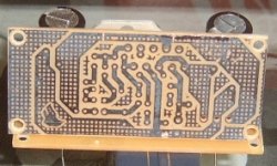
In other news - The amplifier PCB's, previously stuffed up, are now etched and drilled and the LM3876T Chips sit nicely in place
Regards
Foo
I will bare the heat sink 'extensions' in mind. I'm sure I can lay my hands on some when needed.
I will review additional venting once I have got as far as building my enclosure but I will have 'under board' vents to allow the flow of air.
Headphones - Now that's a natty little circuit to add. Nice, simple and immediate. The circuit I have been looking at uses 'cross feed'. I am intrigued by the idea.. But it is a project for later, once the main build is done.
At the moment the headers for power from the regulators to the amplifiers is 29mm as the crow flies so there should be no issue keeping things short and tight.
In other news - The amplifier PCB's, previously stuffed up, are now etched and drilled and the LM3876T Chips sit nicely in place
Regards
Foo
Attachments
Very soon after this point, you will want to have a "light bulb tester" (crude ammeter safety test device) constructed and available for use.
Hi there
It's on the shopping list under 'Lamp Limiter' 🙂
Progress -
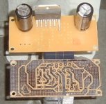
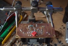
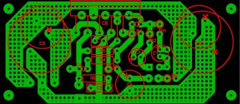
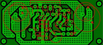
One Amplifier PCB populated. One minor **** up discovered! This has been solved but I have had to correct the PCB pattern. Basically the large electrolytic caps that sit across +ve, GND, -ve, during the corrective redraw, were placed erroneously back in place. Well one of them was.
Instead of spanning the +ve, GND I had set it to +ve, -ve! The fix was only to drill a new hole in the current PCB's and bend the relevant lead over to the GND trace. A mere 5mm distant.
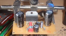
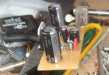
So here are some images of the board. You can see in the 'side view' the stack of 10R resistors, one is under the PCB, that make up the 2.5R resistor value for R6. The poly cap under the PCB is between the GND pin and -ve pin of the LM3876.
You will also notice the left hand cap is slightly forward on the PCB. This is due to the 'fix' to get it connected up correctly.
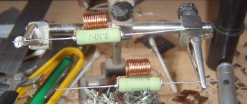
Also see the 9.1R 5W resistors with the .7uH inductor in parallel.
I only have to populate the 2nd PCB and that is the first major works out of the way.
I have an order going in to RS and I will be getting the heat sinks for the amps and 20 poly caps to snub the rectifiers and the secondary coils. It's all very exciting isn't it 😀
regards
Foo
It's on the shopping list under 'Lamp Limiter' 🙂
Progress -
One Amplifier PCB populated. One minor **** up discovered! This has been solved but I have had to correct the PCB pattern. Basically the large electrolytic caps that sit across +ve, GND, -ve, during the corrective redraw, were placed erroneously back in place. Well one of them was.
Instead of spanning the +ve, GND I had set it to +ve, -ve! The fix was only to drill a new hole in the current PCB's and bend the relevant lead over to the GND trace. A mere 5mm distant.
So here are some images of the board. You can see in the 'side view' the stack of 10R resistors, one is under the PCB, that make up the 2.5R resistor value for R6. The poly cap under the PCB is between the GND pin and -ve pin of the LM3876.
You will also notice the left hand cap is slightly forward on the PCB. This is due to the 'fix' to get it connected up correctly.
Also see the 9.1R 5W resistors with the .7uH inductor in parallel.
I only have to populate the 2nd PCB and that is the first major works out of the way.
I have an order going in to RS and I will be getting the heat sinks for the amps and 20 poly caps to snub the rectifiers and the secondary coils. It's all very exciting isn't it 😀
regards
Foo
Attachments
- Status
- Not open for further replies.
- Home
- Amplifiers
- Chip Amps
- New amplifier...possibly..