Hello all
It's been a long while since I was last here. Life has just been too hectic and other projects have been getting in the way.
I have been planning for a long while to have a bash at building my own amplifier. One of the LM38** family in all likely hood. But for my first foray I happen to have a pair of TDA1562Q IC's to hand.
I was going to build a pair of circuits from an Elektor magazine but since starting to dip into the forum again I have come across a couple of slightly different layouts. One is a dual PCB and the other a single, and smaller than the single version I have. This is due to the buffer circuitry of my original choice.
I can make my own PCB's, and have been for about 2 -3 years now. I also have a pair of Kenwood car amplifiers which I am going to gut to free up the ali cases for my project.
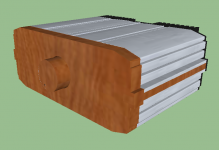
I have some rather nice blocks of wood which I fancy turning into the fascia of the unit as well. The internal void of the case will be 100mm H x 210mm W x 170mm D. I am hoping to fit the pair of amps and the single transformer inside but I have to do some research on physical size and form to see if this is feasible.
The ali cases will be fitted base to base probably with a wood fillet between the 2 ends a wooden fascia, as mentioned, and possibly a heat sink filling the rear void. Speaker wise I have a pair from my old Akia Stereo which has resided in storage for about 4 years. Twin tape, triple CD changer, FM radio with surround sound......That never seemed to work IMO. They will do for now I guess but I will move on to making my own speakers at some point.
I hope to etch the PCB's this coming week and have them populated soon after. The PSU may take a little while longer to do. I need a 240V transformer with a pair of secondary windings that can supply 10A tops. This should give enough headroom I hope.
Probably a CD player will be the source either a PC rom drive or an old playstation. Would anyone have a recommendation, if required, as to whether a buffer of some sort between the source and the amp would be advisable?
regards
fooboo
It's been a long while since I was last here. Life has just been too hectic and other projects have been getting in the way.
I have been planning for a long while to have a bash at building my own amplifier. One of the LM38** family in all likely hood. But for my first foray I happen to have a pair of TDA1562Q IC's to hand.
I was going to build a pair of circuits from an Elektor magazine but since starting to dip into the forum again I have come across a couple of slightly different layouts. One is a dual PCB and the other a single, and smaller than the single version I have. This is due to the buffer circuitry of my original choice.
I can make my own PCB's, and have been for about 2 -3 years now. I also have a pair of Kenwood car amplifiers which I am going to gut to free up the ali cases for my project.
I have some rather nice blocks of wood which I fancy turning into the fascia of the unit as well. The internal void of the case will be 100mm H x 210mm W x 170mm D. I am hoping to fit the pair of amps and the single transformer inside but I have to do some research on physical size and form to see if this is feasible.
The ali cases will be fitted base to base probably with a wood fillet between the 2 ends a wooden fascia, as mentioned, and possibly a heat sink filling the rear void. Speaker wise I have a pair from my old Akia Stereo which has resided in storage for about 4 years. Twin tape, triple CD changer, FM radio with surround sound......That never seemed to work IMO. They will do for now I guess but I will move on to making my own speakers at some point.
I hope to etch the PCB's this coming week and have them populated soon after. The PSU may take a little while longer to do. I need a 240V transformer with a pair of secondary windings that can supply 10A tops. This should give enough headroom I hope.
Probably a CD player will be the source either a PC rom drive or an old playstation. Would anyone have a recommendation, if required, as to whether a buffer of some sort between the source and the amp would be advisable?
regards
fooboo
Attachments
Hi There
Going through my component storage, electronic components, I have found an LM3876T I ordered last year from rapid when I first became interested in making my own.
I am placing a small order this week for parts for a pair of voice mods for some American friends so I am going to order a second LM3876T so I am good to go once I have the first project sorted.
I also have some 0.9mm Enamelled copper wire on the way that was for the first design of 1562 amplifier I looked at. As the design I settled on doesn't require the use of this wire to make coils it was redundant.... Except for the fact the LM3876T circuit does require the use of the same wire 😀
My drive for this project is down to an experience I had in my youth. In the audition room of a 'specialist audio shop'. A pair of Mission 761i speakers hooked up to an ARCAM amplifier and CD player. Sleek, very plain and unassuming. Until the familiar first notes of 'BAD', by U2, on the Live under a blood red sky album drifted, apparently out of nowhere. I was, to say the least, transfixed. It's an album I knew inside out but to be able to hear the little details brought into much more clarity than I had ever heard before.
Sadly things went a bit belly up an I never had the funds to buy my dream set up. It also never occurred to me, back then, to build it myself. If I can only build something that performs a 10th as well I my well be happy.
regards
Fooboo
Well your on the right track, keep at it and keep us posted.
I can't tell you weather or not you need to buffer your input, perhaps someone with more experience can advise on that.
Sounds like a fun project.
I can't tell you weather or not you need to buffer your input, perhaps someone with more experience can advise on that.
Sounds like a fun project.
With a non-inverting amplifier, its probably unnecessary to add a buffer.
Also, with a one-piece car bridge chip, its probably unnecessary to add a buffer.
However, you will probably need a 10k potentiometer.
Also, with a one-piece car bridge chip, its probably unnecessary to add a buffer.
However, you will probably need a 10k potentiometer.
Hi there
That sounds fair enough to me and I'm sure I can handle the 10K pot to boot 😀
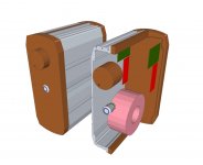
I've been doodling in sketchup and based on the possible transformer, regulator PCB's and the amp boards I've come up with a slightly different 'concept'.
The proposed enclosure now stands on it's end. Internally the traffo is at the bottom which will help stabilise the unit. Amp boards at the top and regulator boards just under these. The idea being to help keep the AC lines away from the audio IN/OUT. The pot will be fitted as near as possible to the PCB's so a shaft will be needed to connect it to the control knob at the front.
As a minor detail a bulgin anti vandal switch will be used to operate the unit. I'm currently (you see what I did there?) Reading up on traffo's and regulators as the required power will dictate what size traffo I end up with. So long as I can fit it in the proposed case with everything else all will be well.
Now in a lateral bit of thinking I am hoping I can just bolt the chips to the case, as per the original occupant, The walls are very thick and there is a lot of surface area to act as a heat sink.
In a slight sideways step in this convoluted path to home build amp ownership I am getting a PC cdrom audio adapter, after Christmas, to set up a CDROM player for the use of. I saw this idea mentioned on this forum and it sounds good to me!......... I hope it does when it's done!!
A slight fly in the ointment is rapideonline no longer stock the LM3867 🤐 So cricklewood will be my next stop off!
regards
Fenris
That sounds fair enough to me and I'm sure I can handle the 10K pot to boot 😀
I've been doodling in sketchup and based on the possible transformer, regulator PCB's and the amp boards I've come up with a slightly different 'concept'.
The proposed enclosure now stands on it's end. Internally the traffo is at the bottom which will help stabilise the unit. Amp boards at the top and regulator boards just under these. The idea being to help keep the AC lines away from the audio IN/OUT. The pot will be fitted as near as possible to the PCB's so a shaft will be needed to connect it to the control knob at the front.
As a minor detail a bulgin anti vandal switch will be used to operate the unit. I'm currently (you see what I did there?) Reading up on traffo's and regulators as the required power will dictate what size traffo I end up with. So long as I can fit it in the proposed case with everything else all will be well.
Now in a lateral bit of thinking I am hoping I can just bolt the chips to the case, as per the original occupant, The walls are very thick and there is a lot of surface area to act as a heat sink.
In a slight sideways step in this convoluted path to home build amp ownership I am getting a PC cdrom audio adapter, after Christmas, to set up a CDROM player for the use of. I saw this idea mentioned on this forum and it sounds good to me!......... I hope it does when it's done!!
A slight fly in the ointment is rapideonline no longer stock the LM3867 🤐 So cricklewood will be my next stop off!
regards
Fenris
Attachments
Its TDA1562Q that needs the 10k pot.
The popular National Semiconductor gainclone projects normally use a 20k pot in parallel with a 22k resistor for input load. Its still about 10k to 11k.
You might have a look at Rod Elliot site for the article "a better balance control" which is also an interesting proposition.
And there are also law fake arrangements using a Log pot for its slightly higher accuracy, paralleled with a resistor to cause something very much like audio taper. That makes a cheap pot perform just about like an expensive pot. 🙂
The vertical orientation will get better performance from the case as a heat dissipater.
This is not a common arrangement, but will work well and will take up less shelf space, since we are not allowed to stack power amps on top of each other.
This is not a common arrangement, but will work well and will take up less shelf space, since we are not allowed to stack power amps on top of each other.
Hi there
@Daniel - Oh yes for the TDA it is. I've been browsing Rob Elliot's site, an excellent resource, for some time. Coincidently it was the Googling of fake law pots that got me there, months ago, on a different project. I was short of a 10K log pot for a project and learned how to make a linear pot work for the volume control; which it indeed does 😀
@Andrew - Cheers 🙂 With the layout as is it also gives me a lot of empty space that could be used for any additions to the set up. Selector, buffer, phono pre-amp, soft start, speaker delay. Up to a point I can thicken the wood strips to increase the width of the unit but I wouldn't want to overdo this.
Without the strip spacer the enclosure width is 100mm Ext/90mm Int. The next option adds 10mm and as a maximum option a total of 30mm added. anything beyond this and I think the unit will start to look too squat. I have the minimum of tools to work the aluminium and again for the wood. But I should get by.
The overall size is 284mm H. 170mm D and 100mm, 110mm or 130mm W.
For now I am perusing the forum trying to find the thread that indicated how to work out transformer size based on speaker Ohm/watts and volts..
Onwards and upwards
regards
Fenris
Attachments

Transformer size that offers good $ value for electrical performance is defined very easily as follows:
VA = one to two times the total maximum output power for a ClassAB amplifier.
eg.
two channels each of 60W will play well with a transformer from 120VA to 240VA.
The same amplifier will also play/operate with transformers outside this VA range.
Conditions are: playing all music styles in all domestic situations. PA and Sound Reinforcement and motor driving and all other exceptional duties need a much better model.
Hi Andrew
Thanks for that. I'm looking at a range that starts at 160VA. They are toroidal with a single primary (230VAC) with dual secondary windings. I think given the specs from the PDF, see below, 2 X 15V secondary coils would be the way to go. But I am not sure what Ampere they need to be. The original 1562 circuit I was going to do recommended a 9A minimum. Would that stand for this version as well?
Here's a link to the document for easier reference -
50+ watts from a 12 V battery.pdf - File Shared from Box - Free Online File Storage
Measurement results (at Ub=14.4 V)
Supply voltage - 8–18 V
Sensitivity - 760 mV r.m.s.
Input impedance - 70 kΩ
Power output - 54 W r.m.s. into 4 Ω (f=1 kHz; THD+N=1%)
Harmonic distortion (THD+N) - at 1 W into 4 Ω: 0.046% (1 kHz)
0.29% (20 kHz) - at 35 W into 4 Ω: 0.12% (1 kHz)
0.7% (20 kHz) - Signal-to-noise ratio (with 1 W into 4 Ω)
88 dBA
Power bandwidth
7.5 Hz – 185 kHz (at 25 W into 4 Ω)
Quiescent current
about 135 mA (‘on’)
I am also thinking of running the PSU side of the circuit as a 'snubberised' type rather than fully regulated.
regards
Fenris
Another question if I may -
Transformers -
Single primary dual secondary -
If the output is rated at 5A I was given to understand this was per secondary.
If these secondary coils were connected in series then the voltage output doubles but the Amps would halve?
If the secondary coils were connected in parallel then the voltage is unchanged but the Amps would double?
What happens if the primary coil is a pair. In this case 115V - 115V which are connected in series to suit the UK 230V mains supply. But the primary is rated at, for example 225VA. Is this per coil and is it affected in the same way, series halves the VA parallel doubles the VA?
regards
Fooboo.......... Also known as Fenris on another forum hence the change in signature LOL
15+15vac? Not for SPIKE system equipped chips LM3875, LM3876, LM3886, LM4780. They have terrible clipping performance when underrun. They're not bridged chips!
A 22+22vac 4.5a transformer is typical for non-inverting gainclone (see the Audiosector forum). That transformer selection is also used for the MyRef amplifiers, which are better quality than most chip amplifiers.
A 20+20vac transformer is about as low as you go on voltage without requesting noise. At this point, if you should happen to need to drive a stouter load, make a parallel amplifier instead of dropping voltage into hard clipping underrun noise. Don't drop to 18+18vac or 15+15vac transformer--make parallel amp instead of promoting hard clipping on spike system chips.
Instead of always wrong voltage. . .
If making a parallel amplifier, you can use a 25+25vac transformer. A parallel amp is neither underrun for voltage nor overrun for current. No two chips pipe up with spike system noise at the exact same instant in time and thus Parallel turns most of that racket into a small amount of heat. A Parallel amp is an excellent opportunity to have the clarity of a non-inverting NatSemi chip amp, but without most of the caveats.
Another opportunity to have a powerful and clear amplifier exists with a slightly different sort of chip. A driver chip amp is a discrete solid state amplifier with the construction ease and clarity of a chip amp, and with the current handling ease of a parallel chip amp. The driver chip method is especially good with large size pre-insulated output devices, since thermal management is so much easier that way. It is a competitor to the Parallel LM3886, but it supports a wide voltage range, and a great deal more current, since the thermal interface is approximately double.
The parallel chip amp and the driver chip amp are the cases where you're not faced with making a dramatic drop in voltage in trade for an insufficient drop in heat. So, ask yourself if you wanted more than 50 watts. 🙂
Hi Daniel
I should clarify. The current build will be the TDA1562 which can run from 8 - 18VDC. Obviously I'd prefer to run as high as reasonable and the 15V output seems like a good start. This unit is also a single rail unit
Once I have cut my teeth on this build then I will go onto the LM3876 build. Which I am aware needs a goodly amount of volts to get the best out of it. Dual rail power supplies intrigue me. So lots of fun to be had I think!
regards
Fooboo
Transformer amperage?
Even with a very small audio amp, a linear unregulated supply needs a minimum 4 ampere transformer. Its like woofers or bells--do you want a little one or a big one?
If these things are too small you get no bass, And, in that case, after amplifying error, what you get is really loud mid-range. Retail mass market amplifiers often combine the too small transformer with the Baxandall bass and treble controls or equalizers. Instead of a mess like that, hi-fi amplifiers normally use larger size transformers.
Usually, a smaller transformer will need a regulated and/or capmuli power supply, effectively blocking the effect of the transformer on audio.
Another caveat of a too small transformer is exactly like a too small battery charger--a capacitor that's not full is an open door to noise, and so the theory of piling up a lot of caps simply doesn't work if the insufficient transformer can't QUICKLY keep them fully charged at all times.
But, with a power amp, there's no fix to the too small transformer problem that costs significantly less than buying a larger transformer that doesn't have the problem. 🙂
Hi Daniel
I should clarify. The current build will be the TDA1562 which can run from 8 - 18VDC. Obviously I'd prefer to run as high as reasonable and the 15V output seems like a good start. This unit is also a single rail unit
Once I have cut my teeth on this build then I will go onto the LM3876 build. Which I am aware needs a goodly amount of volts to get the best out of it. Dual rail power supplies intrigue me. So lots of fun to be had I think!
regards
Fooboo
Your 15vdc single rail is approximately similar to a car with the engine on and its 14.8vdc while charging its battery.
There are heavy duty SMPS available at 20a and 30a with a little adjustable dial that can be run up to a bit over 14vdc. These usually come with a 60mm loud fan that can be replaced with an extra slow 92mm or 120mm quiet fan. Adding even a small amount of resistance, such as 10R in series with the fan will mute most of the motor noise.
SMPS infers switching technology that spends at least half its time asleep and therefore needs derating of at least 50% for steady current demands. That's why a computer with a 200w draw needs a 430w SMPS power supply for it to last longer than a few months. SO, the 30a model is workable for a stereo audio amp as long as the average current doesn't exceed 15a.
When combining car chips with a computer, you have three options for avoiding the loud buzz.
1). The power supply is class 2 double-insulated that comes factory equipped with a 2-prong cord--For example a 90w 15v laptop power pack is available this way, and you might could use one per each amplifier (one for right and another for left).
2). Use a battery powered computer that is never plugged in during music playback.
3). Buy an input transformer for isolation.
With option #1 above, the metal cases are problematic. You could increase safety slightly by adding several coats of clear lacquer. The computer, of course, will ground the case well enough for noise, but not well enough for safety. A problem remains.
Its a job for a ground loop breaker. Here's Rod Elliot on the subject: Earthing (Grounding) Your Hi-Fi - Tricks and Techniques
Please not that the pinouts of the standard rectifier bridge are located differently than the confusing photo in the schematic, and do have a glance at the datasheet.
Here is a text description of a ground loop breaker--All of the following items in parallel with each other:
A diode forwards
A diode forwards
A diode backwards
A diode backwards
A 10w 10 ohm resistor
A 100nF cap.
This unit is a ground loop breaker. One end connects to earth ground and the other end connects to power star ground. The ground loop breaker needs to be of sufficient strength and hold up time so that it would be able to blow the mains fuse or trip the mains breaker.
Other thoughts: Its great to ground amplifiers, but its terrible to ground humans (electrostatic discharge, ESD), so I'm glad that the front panel of your amplifier is non-conductive. But, I'd be happier if the entire thing was non-conductive. That can be fairly important for a car chip that isn't in a car. The tab of the car chip is power star ground.
Hi Daniel
Thanks for the info. A lot to ponder and digest..My head hurts!
A bit of digging around on NUUK's, excellent, site has answered several questions. I now know I can get a -
120VA, 160VA or a 225VA toroidal unit. Any of the 3 have 2 X 12VAC secondary coils and the Amps start at 5A, 6.67A and 9.38.
The output after rectification, no load, will be around 16.92V so well in range for the TDA1562Q amp chips.
Safety wise - Oh yes indeed. I am well aware of the risks and my responsibility to others and myself. There may well be a paint job on the raw aluminium. But regardless the casing halves will be electrically strapped together and the single rail regulator circuit will be wired out with the ground break loop. NUUK's and Mr Elliots site have been referenced for this.
The Amp chips themselves will be insulated with either mica or a silicon pad from the case. Also, particularly, as this is likely to be my first 'practical' mains power interface build an RCD plug will be used to ensure the maximum possible safety.
At 44 years old I can proudly say, without being smug, I have only been electrocuted once. When I was 3 and I stuck a wet match into a W. German AC socket. The flight across the toy room was sudden and very fast! The look on my Mums face is still etched in my memory 😱
regards
Fooboo
It may be slightly over 17v, just a tiny power surge away from blowing the amp. So, here are a few things to consider.
Consider capmulti power supply.
Consider the unwind-rewind feature of toroid transformers that can help fine tune the output voltage (just by winding around or unwinding a very small amount).
In addition to the mild transformer adjustment, Consider using KBPC2504 with 4 of 10nF lossy polyester dip caps in the popular receiver style rectifier. It should drop almost 1v of peaky noises that weren't going to be useful for amp power anyway. Also for dropping noise and thus a tiny bit of voltage as well, consider a PI filter.
Consider an LED drainer combo: At the slight cost of causing tiny noise in trade for decreased risk, you could use a resistor and an amber LED (run up to ~40%, see the led datasheet and online led calculator) at a position close to the rectifier (and with the resistor(s) to the ground side). I favor a 2v Amber diode, so that when the light is out, there's only 2v of shock left in there instead of an extreme charge. I call it the "keep fingers off" light. This slightly less effective version of a drainer is better than none at all, and it will still effectively burn up some extraneous ac noise voltage so that little extra bit doesn't charge up caps. If you need a panel light, the led can actually be cabled to the front of the enclosure via twisted pair.
P.S.
Since you already have beautiful enclosures, you'll still be weeks ahead of me on a given project.
Hi Daniel
Or I will have to add a regulator to each side to 'lock' the peak voltage. An LM317 or the like.
Failing that there is another alternative. Two transformers. 80VA each 9V per secondary and parallel each secondary to get 9A. Expected output after regulation would be around 12.67V. This would allow greater headroom for any power on surge/AC mains variance.
The smaller spec transformers also have a smaller physical size.
Weeks ahead..........Only if I actually start doing something! LOL
regards
Fooboo
Car chips are designed to be inexpensive, so here are some clean SMPS options.
For Stereo (one power supply):
20a SMPS adjustable (adj to about 14vdc)
For Monobloc/DualMono (two power supplies):
10a SMPS adjustable (adj to about 14vdc)
7a SMPS 15vdc
6a SMPS 15vdc
Add the ground that doesn't buzz:
Note that these all have a two conductor AC input, and that these examples assume that you will add your own 3 conductor AC cord along with a ground loop breaker circuit.
Laptop pack:
The little 6a inexpensive laptop cords works fine if you have an 8 ohm speaker, but not enough power for running your amplifier with a 4 ohm speaker. The laptop version assumes it will charge a battery and so it needs a Low Impedance 3300uF (or so) cap on the end of its DC cord. An inexpensive Nichicon PW will do, or a Panasonic FC, or an Elite PS (105c) or anything Low ESR. Its easy to locate that part at the DC input jack of your amplifier enclosure.
Edit,
I have all of these power supply types. The one that's running my car chip amp is the 15v 90w laptop pack. Yes, that amp has 8 ohm speakers on it. . . and because of that, the demand is well within range for the laptop pack.
Last edited:
- Status
- Not open for further replies.
- Home
- Amplifiers
- Chip Amps
- New amplifier...possibly..