Before you fire up the amp, make sure you have a fuse in the primary.
Also, a variac or a light bulb currently limiter jig is highly recommended.
1. You don't need a load at the output.
2. I measured the B+, B-, voltage across the 3W 0.47R, and DC offset.
Have fun!!
Also, a variac or a light bulb currently limiter jig is highly recommended.
1. You don't need a load at the output.
2. I measured the B+, B-, voltage across the 3W 0.47R, and DC offset.
Have fun!!
When i turn on my aleph mini i get an offset of approximately 300mV on my speaker out wich drops in about 4-5 seconds to 30mV. Is this normal and do I need to do something to protect my speakers?
hi all
are these boards still availiable
im after 4x output boards to turn my mini a aleph 5 into a 4
mine are the original brian gt mini a boards
regards sheafer
are these boards still availiable
im after 4x output boards to turn my mini a aleph 5 into a 4
mine are the original brian gt mini a boards
regards sheafer
Before you fire up the amp, make sure you have a fuse in the primary.
Also, a variac or a light bulb currently limiter jig is highly recommended.
1. You don't need a load at the output.
2. I measured the B+, B-, voltage across the 3W 0.47R, and DC offset.
Have fun!!
Just tested today, both amps seem Ok.
I've measured 5mV at the output (DC Offset).
Forgotten the voltage for the 0.47R... 😡 I'll measure tomorrow.
Is it correct ? 😕
A 5mV DC offset is very low. Great to hear you've fired up the mini Aleph Korben69!
The voltage across the 0.47R and Ohms Law give the bias current your mini Aleph is running at. I = V / 0.47, in a normal mini Aleph V is about 0,5 volts resulting in a bias current of ~ 1 ampere.
When my transformer arrives I'm also gonna wire everthing together and fire up mine. I'll keep you posted.
5mV is excellent. I think mine is at 25mV, and I don't bother to go lower. I would rather spend the time on listening 🙂 FWIW, my bias measures 0.47V across a 0.47 // a 1R, that will be around 1.47A.
I've got 0.450 v at the 0.47R, less than 1A.
For DC offset I've tried with another DMM, the value is about 30mV decreasing.
Now I've to connect in real life and listen... keep you informed
For DC offset I've tried with another DMM, the value is about 30mV decreasing.
Now I've to connect in real life and listen... keep you informed
Less than 1 ampere... You might have to lower the 0.47R resistors to increase the bias current a bit. As Grey Rollins, without whom this thread wouldn't exist, said:
"Never underestimate the sonic benefits of higher bias. Just make sure you can manage the heat."
"Never underestimate the sonic benefits of higher bias. Just make sure you can manage the heat."
Less than 1 ampere... You might have to lower the 0.47R resistors to increase the bias current a bit. As Grey Rollins, without whom this thread wouldn't exist, said:
"Never underestimate the sonic benefits of higher bias. Just make sure you can manage the heat."
Ok, but which one ?
Based on BrianGT boards does it mean R23/24/27/28 on AMP board ? 😕
Should I try 0.33 ?
Last edited:
Ok, but which one ?
Based on BrianGT boards does it mean R23/24/27/28 on AMP board ? 😕
Should I try 0.33 ?
From what I've read here, yes those are the resistors to change. Difficult for me to say which value to use without knowing the size of the heatsinks. Perhaps 0.39R, you can of course make all kinds of values by soldering parallel resistors to the 0.47R's
You only need to lower R27 and R28. You can leave the 0.47 there and simply parallel a higher value of resistor.
What I did was to start // the 0.47R with a 2R 1W, ran it for a couple days, checked the heat sink for excessive heat, and checked the transformer for overheat and hum. If everything checked out, I lower the 2R to 1.5R and repeated. At the end, I settled on 1R // 0.47R, YMMV.
What I did was to start // the 0.47R with a 2R 1W, ran it for a couple days, checked the heat sink for excessive heat, and checked the transformer for overheat and hum. If everything checked out, I lower the 2R to 1.5R and repeated. At the end, I settled on 1R // 0.47R, YMMV.
You only need to lower R27 and R28.
Grey Rollins posted that the series resistors in the output need to match the source resistors.
I don't have a schematic with me, but if you mean the series resistors at the output (which are the only other .47 Ohms resistors I can think of), then yes, they should match the MOSFET Source resistors.
What gives? 😕
Thanks Beftus !
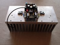
It has been cut in two pieces, one for each chanel.
A higher bias will be Ok with this one, I think so, don't you ? 😉
I've to design the others panels parts, the worst for me, drilling and so...
I'm not equiped to perform that actually.
It has been cut in two pieces, one for each chanel.
A higher bias will be Ok with this one, I think so, don't you ? 😉
I've to design the others panels parts, the worst for me, drilling and so...
I'm not equiped to perform that actually.
I think you can run it at a higher bias than 1 amp with such heatsinks.
I bought a ready made case from Hi-Fi 2000 in Italy. Like you I'm not equipped to do such work. The only thing I had some else do for me was drill and tap the holes for mounting the mosfets to the heatsinks.
Here's my case:
I bought a ready made case from Hi-Fi 2000 in Italy. Like you I'm not equipped to do such work. The only thing I had some else do for me was drill and tap the holes for mounting the mosfets to the heatsinks.
Here's my case:
An externally hosted image should be here but it was not working when we last tested it.
I think the series resistors are for the feedback. Yes, you can do the same by parallel the same value of resistors to them as well. I just didn't bother to change them as I didn't really hear much of a difference, but my ears are not that good either 🙂
Keep in mind, watch the heat dissipation. Another thing is the transformer regulation.
I use an Avel Lindberg 250VA. When I upped the bias, the B+/B- actually were lowered a little. At the current bias, it actually hums a little, a sign that it can take no more beating.
Keep in mind, watch the heat dissipation. Another thing is the transformer regulation.
I use an Avel Lindberg 250VA. When I upped the bias, the B+/B- actually were lowered a little. At the current bias, it actually hums a little, a sign that it can take no more beating.
- Status
- Not open for further replies.
- Home
- Amplifiers
- Pass Labs
- New Aleph Mini PCB GB