Cathode Feedback requires more driver voltage swing.
That somewhat defeats one of the purposes of the design of the 7591 (low drive requirements).
Most circuit topologies have one or more tradeoffs.
Really?
Just make an Executive Decision for yourself, build it, and live with it.
Or make two mono-block amplifiers with each and every topology, and try them all, in Your system.
Is there a WAF problem here?
Using an example of a push pull UL transformer with 40% UL taps, the impedance that the screen has to drive is only 16% of the impedance the plate has to drive.
The screen impedance is not real low at low and medium drive levels.
But I bet the only time the screen contributes any reasonable amount of power to the loudspeakers is when the plate voltage is very near the cathode voltage, which causes very large screen currents (where the screen may be struggling to keep from melting).
Calling such an effect "Distributed Load" is not my idea of a correct term.
Yes, 100% plate load, and 16% screen load.
That is just like struggling with $15 dollars per hour; versus $195,000 per year salaries.
Calling that mode of operation Either "Ultra Linear", Or "Distributed Load" hides the truth.
Please find a new descriptive name for that mode.
Do not get me wrong.
A couple of my own designs use "UL" / "Distributed Load".
They are currently my favorite amplifiers (Oh, did I mention one is SE, and the other PP)?
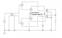
jhstewart9,
When you built a DC coupled all Triode UL, what did the bias circuitry, and other resistance values look like?
That took some pretty complex calculations, right?
Or were the output tubes RF triodes that like to run with grid current?
When you built a DC coupled all Triode UL, what did the bias circuitry, and other resistance values look like?
That took some pretty complex calculations, right?
Or were the output tubes RF triodes that like to run with grid current?
All Triode UL, How it works
The pdf on cct description details how I got there.
Nothing magic, it simply works.🙂
The pdf on cct description details how I got there.
Nothing magic, it simply works.🙂
Attachments
I thought there was a 7 series tube that is direct coupled from first section's cathode to second section's control grid internally, but it also has a resistor from cathode to cathode to load the first section's cathode.
These are great ideas, but I would not "go into production" with any of these tubes today.
These are great ideas, but I would not "go into production" with any of these tubes today.
Last edited:
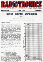
Amplifiers & Superlatives
A paper by DTN Williamson & PJ Walker, 1952 on UL & cathode FB, a very good read. And some worked examples of how the degree of UL FB controls rp (plate resistance).🙂
A paper by DTN Williamson & PJ Walker, 1952 on UL & cathode FB, a very good read. And some worked examples of how the degree of UL FB controls rp (plate resistance).🙂
Attachments
-
Amplifiers-and-Superlatives.pdf118 KB · Views: 134
-
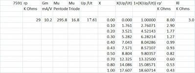
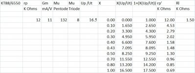 6550_KT88 rp vs UL FB Factor.jpg90 KB · Views: 99
 -
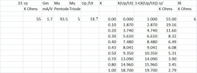 33 rp vs UL FB Factor.jpg89.1 KB · Views: 89
 -
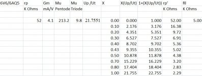 6V6_6AQ5 rp vs UL FB Factor.jpg88.6 KB · Views: 88
 -
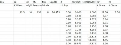 6L6 rp vs UL FB Factor.jpg85.3 KB · Views: 254
 -
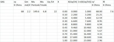 6K6 rp vs UL FB Factor.jpg90.1 KB · Views: 249
 -
 6F6 rp vs UL FB Factor.jpg91.2 KB · Views: 257
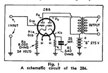
Does the 7591 have the most plate dissipation in that size envelope?
When I assembled my first Heathkit in 1965, I was amazed so much oomph could be produced from a small tube. They still impress.
When I assembled my first Heathkit in 1965, I was amazed so much oomph could be produced from a small tube. They still impress.
I thought there was a 7 series tube that is direct coupled from first section's cathode to second section's control grid internally, but it also has a resistor from cathode to cathode to load the first section's cathode.
These are great ideas, but I would not "go into production" with any of these tubes today.
There may have been a 7V version, don't know. Alan Douglas who could probably have told us died a few years ago. Alan was a Cornucopia of historic tube information. He authored books on tube checkers, but I've never seen anything on specific tubes except for his comments on line.
Another interesting tube in this series of developments was the 2B6, attached.🙂
Attachments
7591 give and take
7591in the early 60's was state of the art for tubes. Fantastic performance suggested by the data sheet. High gain, high current and lower drive voltage made it simple to produce a high power amplifier.
The 7591 has smaller screen drive voltage requirements compared to a 6L6 so if you swap out a 6L6 for a 7591 with no other changes you end up with more negative feedback and so better THD numbers. Add in the drive circuit requirement is much less and the 7591 runs away from the 6L6 given the same circuit.
A lot of companies used this tube and unfortunately the result was not always totally reliably.
The 7591 grid bias voltage being a lot lower than the 6L6 means the bias voltage is more critical in any 7591 design. A bit of bias drift in a 7591 bias circuit can lead to the output tubes "running away" with increasing grid leakage current resulting in the tube drawing ever more power. The data sheet suggests that 330K grid resistors are fine for the 7591 but I found that using such high values really adds to thermal run away concerns. 100K is safer on fixed bias. Another issue with the 7591is the plate/screen dissipation is 19/3.3 watts compared to later 6L6's 30/5 watts. So running a 7591 at full power is living quite close to the edge. The 7591 for the the high gain and sensitivity required close spacing and tight tolerances in the internal construction. This makes 7591 trickery to build consistently.
In my tests the JJ 7591 was not same as the NOS 7591 I had on hand but thought they were "good enough" for keeping older amps going. Then I found the JJ 7591 taller than NOS 7591 and so did not fit into the AA-100 amp I had. The Electro-Harmonix 7591 is the same size as NOS 7591 but the tube characteristics of the Electro-Harmonix 7591 did not measure like a "real" 7591 but more like a 6L6. I ended up using 6n3c-E that are the same size as 7591 but tougher and electrically like a 6L6. I had to modify the bias and drive circuits to get then to work as well as the 7591 they replaced but the end result was quite good.
This is interesting stuff indeed!
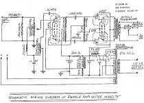
I was reading the 2B6 article. Isn't the circuit in the attached image basically a cathode follower DC-coupled to a power output triode? Or am I not understanding the AC operation of this circuit (the negative feedback)?
--
Another interesting tube in this series of developments was the 2B6, attached.🙂
I was reading the 2B6 article. Isn't the circuit in the attached image basically a cathode follower DC-coupled to a power output triode? Or am I not understanding the AC operation of this circuit (the negative feedback)?
--
Attachments
This is interesting stuff indeed!
I was reading the 2B6 article. Isn't the circuit in the attached image basically a cathode follower DC-coupled to a power output triode? Or am I not understanding the AC operation of this circuit (the negative feedback)?
--
You are correct. Triode one is a low to medium mu triode, Triode two, the power part is a high mu triode. Many of these old tubes are easily synthesized with common tubes still on the market today at a reasonable price. The tests I did 15-20 years ago simply used paralleled sections of a 6SN7 as triode one & a 6F6 triode strapped but G1 & G2 connected together.🙂
Looking at the 2B6 yesterday, it would be somewhat of a challenge.😱
A paper by DTN Williamson & PJ Walker, 1952 on UL & cathode FB, a very good read. And some worked examples of how the degree of UL FB controls rp (plate resistance).🙂
Thanks for posting that paper. Very interesting. The plots seem to be based entirely on calculations using simplified models. If there are any measurements, the authors haven't provided enough information to allow others to duplicate them. But still very useful.
I just posted my data comparing EL34 distortion in various operating modes (Triode, UL, or Pentode) in a new thread, since it has nothing to do with the 7591A.
Scott
You are correct. Triode one is a low to medium mu triode, Triode two, the power part is a high mu triode. Many of these old tubes are easily synthesized with common tubes still on the market today at a reasonable price. The tests I did 15-20 years ago simply used paralleled sections of a 6SN7 as triode one & a 6F6 triode strapped but G1 & G2 connected together.🙂
Looking at the 2B6 yesterday, it would be somewhat of a challenge.😱
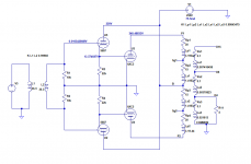
Just to see if it would work, I threw it into LTspice, using a 5687 as the cathode follower half, a 6AC5 as the output triode, and a model of a Hammond 6.6k PP OPT.
It worked!
The only problem is that it looks like it will take a lot of voltage drive to get to full power. Gain of the whole thing (5687CF - 6AC5 - OPT) to the load was well below 1. Or maybe I did something wrong.
Attachments
Using an example of a push pull UL transformer with 40% UL taps, the impedance that the screen has to drive is only 16% of the impedance the plate has to drive.
The screen impedance is not real low at low and medium drive levels.
But I bet the only time the screen contributes any reasonable amount of power to the loudspeakers is when the plate voltage is very near the cathode voltage, which causes very large screen currents (where the screen may be struggling to keep from melting).
Calling such an effect "Distributed Load" is not my idea of a correct term.
Yes, 100% plate load, and 16% screen load.
That is just like struggling with $15 dollars per hour; versus $195,000 per year salaries.
Calling that mode of operation Either "Ultra Linear", Or "Distributed Load" hides the truth.
Please find a new descriptive name for that mode.
Do not get me wrong.
A couple of my own designs use "UL" / "Distributed Load".
They are currently my favorite amplifiers (Oh, did I mention one is SE, and the other PP)?
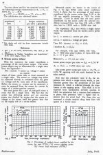
Another article by DTN Williamson, in this one he treats the contribution to the power output by the screens among other things. The rp of the tube as a voltage source drops very quickly, looks like only 10% UL drives rp down by 90%. Very effective.🙂
Attachments
Just to see if it would work, I threw it into LTspice, using a 5687 as the cathode follower half, a 6AC5 as the output triode, and a model of a Hammond 6.6k PP OPT.
It worked!
The only problem is that it looks like it will take a lot of voltage drive to get to full power. Gain of the whole thing (5687CF - 6AC5 - OPT) to the load was well below 1. Or maybe I did something wrong.
The voltage gain of common pentode (6K6, 6F6) stages grid to plate ~15. For later hiGm tubes like the 6BQ5 can be something like 25. Just do Gm*Rl gets a good approximation. So after going thru the OPT, the resulting voltage is a lot less, depends on turns ratio.🙂
A surprise if one has never looked at the output stage in isolation.😱
jhstewart9,
Thanks for the interesting article. It made some things clearer for me.
In the article, I see 13W push pull (6.5W per tube).
0.256W per screen
0.265/6.5 = 0.04
That is 4 % "Distributed Load" power from the screen.
Of course that is for a 20% tap. Although a 40% tap would be easier for the screen current to drive, for a 40% tap versus the 20% tap, the screen voltage would have kept up better to the descending plate voltage, but that would mean there was less current from the screen to drive the 40% UL tap.
Having the author do most of the work for me, made it easy for me to
continue my original conclusion:
There is not very much power delivered to the UL tap.
And that makes me think that "distributed load" is a misleading term.
That is a little like saying that a 200 Horsepower engine delivers 4 more Horsepower when you use Synthetic Oil, instead of traditional 30 weight oil.
The real advantage of Synthetic Oil is less engine wear, not a less significant addition to horsepower.
One real advantage of using a UL tap, is that all other things being equal, it is easier on the screen, versus using the screen in Pentode/Beam Power mode.
Last edited:
The voltage gain of common pentode (6K6, 6F6) stages grid to plate ~15. For later hiGm tubes like the 6BQ5 can be something like 25. Just do Gm*Rl gets a good approximation. So after going thru the OPT, the resulting voltage is a lot less, depends on turns ratio.🙂
A surprise if one has never looked at the output stage in isolation.😱
Ah, good. I guess I was doing it right. You're right, of course the output stage by itself doesn't provide much gain if you include the stepdown ratio of the OPT. Also, the 6AC5 doesn't have huge gm. It would be fun to make this out of paralleled EL84 or EL83 with something like a 5687 for the CF half. Maybe push-pull-parallel with a 12AT7 or 5965 LTP for the phase splitter/driver.
Food for thought. I wish I was better at thinking, though!
jhstewart9 said:Just do Gm*Rl gets a good approximation.
Thanks, that's a good one!
the driver tube is not needed and will destroy the outputs. the grid voltage should be -20 ish volts not +20v that is huge overdrive. The transformer CT should be -20v straight into the 6AC5's with 1k grid stopper resistor.
- Home
- Amplifiers
- Tubes / Valves
- New 7591A Amp Design, 35W x2