I think my prototype operates the 7591A within its published ratings. I’ve attached the 1963 Westinghouse data sheet, which rates the tube for 550v on the plate and 440v on the screen. Westinghouse suggests a pentode-mode operating point of 450v on plate and 400v on the screen, which is similar to my amp. I believe the 7591A was used in a few guitar amps back in its day, which must have been much harder on it than my hi-fi amp prototype.
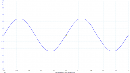
I’ve attached some more data comparing the Tung Sol Reissue 7591A and the Electroharmonix 7591A. I’ve compared the clipping characteristic for the two tubes, each driven to about 1.5% THD, and the Tung Sol Reissue clipping seems much softer to me.
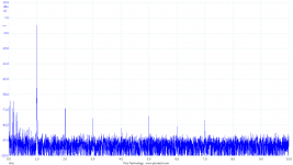
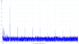
I’ve also compared the distortion spectra of the two tubes at around 12W. The Electroharmonix seems to have a higher proportion of higher-order harmonics.
So, I have mixed feelings about the Electroharmonix. It is quite ruggedly built (see the attached photo), possibly based on the Sovtek 5881. But the Tung Sol Reissue sounds better to me, as I've listened to it over the last few weeks. The EH might be a good choice for a guitar amp.
I’ve designed a version of my PCB which accepts either the 6L6GC or EL34, instead of the 7591A. So, I’ll be able to compare performance and sound in the same circuit when I build it up in the coming weeks.
Scott
I’ve attached some more data comparing the Tung Sol Reissue 7591A and the Electroharmonix 7591A. I’ve compared the clipping characteristic for the two tubes, each driven to about 1.5% THD, and the Tung Sol Reissue clipping seems much softer to me.
I’ve also compared the distortion spectra of the two tubes at around 12W. The Electroharmonix seems to have a higher proportion of higher-order harmonics.
So, I have mixed feelings about the Electroharmonix. It is quite ruggedly built (see the attached photo), possibly based on the Sovtek 5881. But the Tung Sol Reissue sounds better to me, as I've listened to it over the last few weeks. The EH might be a good choice for a guitar amp.
I’ve designed a version of my PCB which accepts either the 6L6GC or EL34, instead of the 7591A. So, I’ll be able to compare performance and sound in the same circuit when I build it up in the coming weeks.
Scott
Attachments


I have converted a Dynaco SCA35 to 6GM5 which is a 7591 in a different tube. The Dynaco output transformers are rated at 35 watts and have a Ulta linear tap around 23%. They were about 7.4k impedance. I used EFB Bias. The result was wonderful. 34.1 watts at 0.71%thd. Whomever recommend the 23% tap has a good plan. But the Dynaco repop transformers. Nice pieces.
If there is interest, I’d be happy to post the revised schematics when the new PCB is done. New amp designs using these reintroduced 7591 tubes seem relatively rare, but I think they deserve more attention.
Very interested in your final schematic. Please post it when you have it ready. Photo of the PCB would be welcome too. Best wishes with your project.
7591A PP Amp Toroidy UL CFB OPT
I connected a 6.6k Toroidy OPT to a Dynaco ST70 type amp. The driver board is the tubesforhifi using a trio of 12AU7's.
Connecting Ultralinear as well as the cathode feedback windings, I get 25 watts per channel at 400vdc B+ into an 8 ohm load.
I connected a 6.6k Toroidy OPT to a Dynaco ST70 type amp. The driver board is the tubesforhifi using a trio of 12AU7's.
Connecting Ultralinear as well as the cathode feedback windings, I get 25 watts per channel at 400vdc B+ into an 8 ohm load.
Attachments

Which model of PicoTech are you using? I have four of them going back more than 20 yrs, very useful.
What output level is the amp running at in the PicoTech results you have posted?
Think you are shewing in the same post some scope shots with clipping. The frequency domain traces don't agree. Also see your PS hum on the freq results.
Looking at your schematic can't see the value of the local NFB resistors from the 7591 plates to the drivers. In any case there will not be much NFB, the resistors have to drive the rp of the 6SN7 drivers, ~10K. Many folks fail to recognize that condition.🙂
Do you have any Damping Factor numbers while running in the various conditions? Always worth knowing. Another useful test is a loudspeaker simulator, test if the amp is stable while driving a complex load.😱
Which model of PicoTech are you using? I have four of them going back more than 20 yrs, very useful.
What output level is the amp running at in the PicoTech results you have posted?
Think you are shewing in the same post some scope shots with clipping. The frequency domain traces don't agree. Also see your PS hum on the freq results.
Looking at your schematic can't see the value of the local NFB resistors from the 7591 plates to the drivers. In any case there will not be much NFB, the resistors have to drive the rp of the 6SN7 drivers, ~10K. Many folks fail to recognize that condition.🙂
Do you have any Damping Factor numbers while running in the various conditions? Always worth knowing. Another useful test is a loudspeaker simulator, test if the amp is stable while driving a complex load.😱
The data were taken with a PicoScope 4262. A very useful instrument, I agree; it does the work of several conventional instruments at a lower cost.
The clipping characteristics in my post #21 were taken at 1-1.5% THD, roughly 37-38W output into 5 ohms. The distortion spectra were taken at 12-13W, as I mentioned. The purpose of those was just to illustrate the differences I observed between the Tung Sol Reissue 7591A and Electroharmonix 7591A. The big difference surprised me, since they are both made by New Sensor.
The local feedback resistors R42-R43 are not used. Early on, I experimented with adding 3.8dB of NFB by making them 220k ohms, but that did not improve performance - in fact, it made it worse. So they are now omitted.
I was wondering if anyone would ask about NFB....... The measurements were made with about 17dB of NFB, from the output back to the cathode of the input stage. In pentode mode, that equates to R60 of 2.2k ohms to the 8 ohm transformer tap, and C20 of 1500pF. I didn't measure damping factor, but it's on my to-do list......... I did verify stability with up to 1uF of shunt capacitance on the output, but I'm still working on the frequency compensation. I won't really finalize the circuit for a few weeks yet.
For now, I'm working on an alternate circuit with EL34 or 6L6GC tubes, to compare the distortion. I have the idea that the 7591A are more linear, but I haven't measured it yet. I'd really like to be able to compare 7591A vs. EL34 or 6L6 in the same circuit, with the same NFB, or open loop. I just don't see much data out there comparing output tube linearity in a meaningful way.
Scott
The data were taken with a PicoScope 4262. A very useful instrument, I agree; it does the work of several conventional instruments at a lower cost.
Most of the tests I do use a PicoScope 3224, 2-channel/12 bit/ 10 MHz. 12 bits theoretically gets 72 db, better than any tube amp I might build!
My first PicoScope more than 20 yrs ago is an ADC-100, 2-channel/ 50 KHz/ 12 bits. Somewhat limited but got me into a different kind of test equipment. Later I bought an ADC-216, 2-channel, 16 bit, ~100KHz, so 96 db was possible. Both the ADC versions are interfaced to the computer via a Centronics cable, not very convenient. There are Centronics to USB adapters available from PicoScope. Generic adapters do not work.
About 10 yrs ago I got a PicoScope 5203, 2-channel/ 8 bit/ 250 MHz. It has a built in ARB, so some interesting tests are possible.
It is possible to get both the 3224 & 5203 running simultaneously, allowing some very interesting tests. Gave away my 2-channel/Hz scope several years ago.
I got a Battery Powered (4X-AA) Differential Probe as well. Great for off ground measurements in the middle of a cct. Rated for +/- 750V.
One attachment is the loudspeaker simulator I use.🙂
The other shews the combined time & frequency domain results of an amplifier in test using the 3224.
Attachments

Your loudspeaker simulator is interesting. I had been thinking of building a simplified version of the Stereophile loudspeaker simulator:
Real-Life Measurements | Stereophile.com
My Maggies present a remarkably uniform 4-5 ohm resistive load across the audio band, but it would be useful to measure performance into a more usual reactive load.
Cheers,
Scott
Real-Life Measurements | Stereophile.com
My Maggies present a remarkably uniform 4-5 ohm resistive load across the audio band, but it would be useful to measure performance into a more usual reactive load.
Cheers,
Scott
That loudspeaker model has been circulating for a while. Got my copy from the English magazine Electronics World, it was a very popular publication.
My version is a little simpler but does very well with common parts.
Not much new under the sun..........or audio!!🙂
A description emailed to cover a query in an article I authored in AudioXpress Magazine-
This is what I hook up to the amp output terminals when I want to simulate a speaker.
It has a nice peak at about 45 Hz, similar to a speaker resonance in it's box. If you need to simulate a reflex enclosure you will need another LC circuit. Other resonant frequencies can be set by changing the Hammond choke or it's resonating non-polarized (NP) capacitor.
The rise of impedance caused by the 90 microhenry choke starts at about 4KHz & is well up at 10 KHz similar to a real speaker.
7591A Used as an RF Linear Amplifier at 3.9 Mhz
Hi All,
I've had similar experiences with the different 7591A types. I still believe that the original Westinghouse branded (or rebranded) types work best. That said, the Reissued Tung Sol is a close second. The 'EH' is not as linear, and the 'JJ' is clean, but down on power.
My application is as an RF Linear amplifier. The 7591A spec's say a plate to grid 1 capacitance of 0.25 pf , whereas the 6L6 variants are 1pf or more. A lower Gp capacitance, and dual G2 terminal at the base make the 7591A an attractive RF tube. A B+ voltage of 600v has not shown to be a problem. I have gotten as much as 80w PEP from a pair.
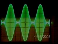
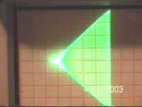
I attach scope waveforms, including the 100% AM modulated envelope pattern, and the trapezoid pattern. The diagonal sides of the Trap are straight lines indicating excellent linearity. This is for original 1960's tubes. The EH when used shows the curvature of an 'S' pattern.
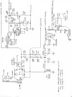
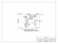
I attach two power supply schematics. The one with Tubes is used in the RF application, and the solid state FET regulator is used in a Sherwood S8000 where the output tubes are 7868's. The 7868/7591/6GM5 are the same tube with differing base type. In my schematic, over the years I put in a 6W6 instead of a 5V6, and a 6CB6 instead of a 6AH6. In the case of the 6AH6, I ended up with a dead short heater to cathode. Later finding that the 6AH6 spec's for V h-k are not well specified, and best not to use this tube for my application. A 6CB6 seemed to be better suited.
One comment about the loop compensation on the regulators is that the loop response time will have an effect on the audio, most notably on the bass frequencies. Too much compensation can lead to a boomy bass response, not enough compensation, the bass gets diminished.
Jim
Wd5JKO
Hi All,
I've had similar experiences with the different 7591A types. I still believe that the original Westinghouse branded (or rebranded) types work best. That said, the Reissued Tung Sol is a close second. The 'EH' is not as linear, and the 'JJ' is clean, but down on power.
My application is as an RF Linear amplifier. The 7591A spec's say a plate to grid 1 capacitance of 0.25 pf , whereas the 6L6 variants are 1pf or more. A lower Gp capacitance, and dual G2 terminal at the base make the 7591A an attractive RF tube. A B+ voltage of 600v has not shown to be a problem. I have gotten as much as 80w PEP from a pair.
I attach scope waveforms, including the 100% AM modulated envelope pattern, and the trapezoid pattern. The diagonal sides of the Trap are straight lines indicating excellent linearity. This is for original 1960's tubes. The EH when used shows the curvature of an 'S' pattern.
I attach two power supply schematics. The one with Tubes is used in the RF application, and the solid state FET regulator is used in a Sherwood S8000 where the output tubes are 7868's. The 7868/7591/6GM5 are the same tube with differing base type. In my schematic, over the years I put in a 6W6 instead of a 5V6, and a 6CB6 instead of a 6AH6. In the case of the 6AH6, I ended up with a dead short heater to cathode. Later finding that the 6AH6 spec's for V h-k are not well specified, and best not to use this tube for my application. A 6CB6 seemed to be better suited.
One comment about the loop compensation on the regulators is that the loop response time will have an effect on the audio, most notably on the bass frequencies. Too much compensation can lead to a boomy bass response, not enough compensation, the bass gets diminished.
Jim
Wd5JKO
My 7591 Observations, both RF and Audio
OK, sorry. I'm getting used to file upload method.
Jim
OK, sorry. I'm getting used to file upload method.
Jim
Attachments
I finally began measurements on my second prototype, which was designed to accept EL34 or 6L6GC instead of 7591A. I had the idea that the 7591A were more linear than other common power tubes, but as it turns out, the three tube types I compared were remarkably similar in terms of distortion.
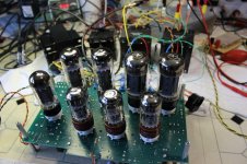
I’ve attached a photo of my prototype, with Mullard Reissue EL34 installed in one channel and Tung Sol Reissue 7581A / 6L6GC installed in the other. And the plot compares the THD vs. Power Output for two different pairs of Tung Sol Reissue 7591A, the Mullard Reissue EL34, and the Tung Sol Reissue 7581A / 6L6GC. The power supply, driver circuit, and output transformers were the same. All tubes were operated as pentodes with a 390v regulated screen supply, and with 17dB of NFB taken from the 8-ohm output tap. The plate supply is 440-450V at no signal, dropping to 400-405V at full output.
The EL34 has the highest plate efficiency and delivers the most power (41W). But the 7591A and 7581A were not far behind at 37W and 37.5W, respectively. And most importantly, the THD of the three types is almost the same. The tube configuration (pentode vs. UL vs. triode) matters much more than tube type. The 6L6GC does not have the reputation of being a very linear tube, but it actually had the lowest distortion at 1W (0.013%) and less than 0.2% THD at 35W.
So, in the end, I’m not sure which I like best. In listening, I think I prefer the 7591A, followed by the 7581A/6L6GC. But I doubt I could tell the difference in a rigorous double-blind test. A sensible person would have just built the amp and been satisfied with it, I suppose.
I started this thread with the observation that the 7591A produced much lower distortion as a pentode than in ultralinear mode, or as a triode, and that’s also true with the EL34! I plan to start a new thread to post those results, since they have nothing to do with the 7591A.
I'll put together a package containing the schematics and parts list, when I've built this thing into a box. My prototype is not exactly safe..... ;-) But first I have to choose between the 7591A and the other types.
Scott
Attachments

WB8PEP,
Thanks for the great scope shots.
You reminded me of some HF linear amplifiers I worked with from Gates (1KW), and Collins (3, 10, and 45KW PEP).
The exciters could do SSB, and AM equivalent (Carrier and one sideband).
Scope measurements taken from RF sample ports were very handy.
Thanks for the great scope shots.
You reminded me of some HF linear amplifiers I worked with from Gates (1KW), and Collins (3, 10, and 45KW PEP).
The exciters could do SSB, and AM equivalent (Carrier and one sideband).
Scope measurements taken from RF sample ports were very handy.
TavishDad,
Thanks for the very interesting continuing saga.
What is the damping factor with 17dB of negative feedback?
What would be really interesting is to see what the distortion of the various manufacturer's tubes are without that 17 dB of negative feedback.
Thanks for the very interesting continuing saga.
What is the damping factor with 17dB of negative feedback?
What would be really interesting is to see what the distortion of the various manufacturer's tubes are without that 17 dB of negative feedback.
Last edited:
TavishDad,
Thanks for the very interesting continuing saga.
What is the damping factor with 17dB of negative feedback?
What would be really interesting is to see what the distortion of the various manufacturer's tubes are without that 17 dB of negative feedback.
I have data like that for the EL34 in various operating modes (triode, UL, and pentode), with and without the 17dB NFB. I'll post it as soon as it is plotted. I don't think I ever took no-feedback data on the 7591A.
Damping factor is still on my to-do list. With the NFB, I'm guessing the output impedance will be a few tenths of an ohm.
Not trying to depreciate your research of great value, but pretty please can you stop calling random partial feedback mode "ultralinear"? 😱
That may lead people to wrong conclusions...
That may lead people to wrong conclusions...
Not trying to depreciate your research of great value, but pretty please can you stop calling random partial feedback mode "ultralinear"? 😱
That may lead people to wrong conclusions...
I don't like the term "Ultralinear" either, but I'm not sure what else to call it to make my meaning clear. "Distributed large-signal feedback to the screens using taps on the output transformer secondary" is a bit much to type...... ;-)
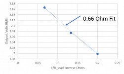
I measured the output impedance at the 8-ohm tap, with the EL34 output tubes in pentode mode and 17dB NFB. I used a 1kHz output signal around 2V RMS and varying load impedances of 15, 7.5, and 5 ohms. Then I fitted a curve to the data - best fit was 0.66 ohms. The same measurement on the 4-ohm tap gave 0.45 ohms. So damping factor for an 8-ohm speaker is about 12, and 8.9 for a 4-ohm speaker. Not great, but adequate, and many commercial tube amps are much worse. Damping in UL or triode mode would be improved, but at the cost of higher distortion. I guess I'm willing to accept slightly poorer damping factor in return for lower distortion.
Scott
Attachments
The general term is "distributed loading", I believe (the "partial feedback" I've used in my previous post is also incorrect as it is a broader term not necessarily related to OPT taps).I don't like the term "Ultralinear" either, but I'm not sure what else to call it to make my meaning clear. "Distributed large-signal feedback to the screens using taps on the output transformer secondary" is a bit much to type...... ;-)
"DL" is quite short 😉
Ultra-Linear
The name was coined & popularized by David Hafler & Herbert Keroes in their articles published in Audio Engineering Magazine, November 1951 & June 1952. Hafler & Keroes worked at Acro Products in Philadelphia. Selling transformers was an objective. The cct was not new, something pulled in from the 1930s & extensively marketed, much like Chrysler did with HEMI.🙂Looks like they were very successful.
Not as effective as cathode FB. But the require OPT was a lot easier to build.
- Home
- Amplifiers
- Tubes / Valves
- New 7591A Amp Design, 35W x2