Bear with me, I'm kind of a dummy...
My understanding was that the 6AC5 is designed to be operated with positive grid voltage, which is why the DC-coupled cathode follower driver is necessary. Did I get that wrong?
My understanding was that the 6AC5 is designed to be operated with positive grid voltage, which is why the DC-coupled cathode follower driver is necessary. Did I get that wrong?
The very high mu (125) 6AC5 was designed for +ve bias operation, Class A2. As such it needs a direct driver that will put it there, usually a triode with a mu of about 10. The result is a composite tube with very pentode like characteristics.
All in one bottle, that would be tubes like 6B5, 6N6G, 25B5 & 25N6G, some of which I referred too earlier in this thread. These are all self biasing.
Just looking at the data sheet depiction of the pinout of these tubes shews two triodes internally connected to get the required result. The input triode has a mu of about 10, the power triode a mu of 50+.
These were used successfully in many ccts in the later 30s & early 40s. The pinout allows them to be stuffed into the same socket as a power pentode, no separate biasing cct required! How Kool is that?🙂
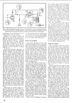
The experimental hookup I used puts no stress on the +ve biased section (6F6) since the screen is paralleled with the control grid, both at low voltage. And it ran a long time while all those measurements were being made.
All in one bottle, that would be tubes like 6B5, 6N6G, 25B5 & 25N6G, some of which I referred too earlier in this thread. These are all self biasing.
Just looking at the data sheet depiction of the pinout of these tubes shews two triodes internally connected to get the required result. The input triode has a mu of about 10, the power triode a mu of 50+.
These were used successfully in many ccts in the later 30s & early 40s. The pinout allows them to be stuffed into the same socket as a power pentode, no separate biasing cct required! How Kool is that?🙂
The experimental hookup I used puts no stress on the +ve biased section (6F6) since the screen is paralleled with the control grid, both at low voltage. And it ran a long time while all those measurements were being made.
Attachments
the driver tube is not needed and will destroy the outputs. the grid voltage should be -20 ish volts not +20v that is huge overdrive. The transformer CT should be -20v straight into the 6AC5's with 1k grid stopper resistor.
The 6AC5 control grids really need to run +ve for linear operation, otherwise the toob would not move to Class A. Zero bias Class B operation is also possible, but cross over distortion is a problem. OK for a Public Address Amplifier or modulator but no exactly hifi.
Gross errors can occur in some simulations, many of the models for tubes either have no provision for +ve bias operation or the model doesn't cover the -ve grid current requirements. Too much +ve bias in a simulation creates no smoke, a good way to go before applying solder!
Triode modelling in Electronic WorkBench has no provision at all for +ve bias operation. My experimental results are Real World, on the test bench.😱
Attachments
the driver tube is not needed and will destroy the outputs. the grid voltage should be -20 ish volts not +20v that is huge overdrive. The transformer CT should be -20v straight into the 6AC5's with 1k grid stopper resistor.
For the 6AC5 even if the grid is running at +13V the grid current is only 5 mA. That calcs out to 65 milliWatts, hardly enough to move the needle.🙂
The Brimar EL506 is the latest iteration of the 7591 /7868. It has a magnoval base and the EH7868 appears to be based on this rather than the older versions that have a Novar base. It also shows the lower grid resistor specification. (I've got six NOS 7868 and a pair of NOS EL506, need to use them for something.)
Later this year I hope to make an UL - CFB SE 7868 with no GNFB and using a 12AT7 SRPP for drive. It models nicely for approx 6 watts out at 17 Watt Pa (absolute maximum is 19 Watt, design center is around 17.3 Watts). Can use a standard EL34 OPT for it.
Schade in Beam Power Tubes mentions that the BPT were originally designed for the screen / beam to be between 250 and 300V and that the screen has to be at least 15V below plate to prevent emission issues and being best to be 15 - 20 volt below plate for optimum functioning. Once build I'll compare against my UL SE EL84 driven by a 2C51 (5670) (which is my favorite amp to date).
AM
Last edited:
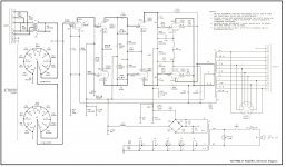
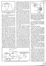
The Westrex-KS-19-602-L1 uses a connection for the screen to the opposite plate - a form of placing the tubes in class B without incurring the crossover penalties. This is similar to what mcIntosh does with their power amplifiers and can lead to excellent results.
This is a further development of the 1964 US 3153766 patent that achieved similar good results by using diodes and ordinary output transformers.
This is of little interest to me since I prefer single ended but if I was to build something in push pull than I would certainly model this and check what (if any)advantages it might show up.
Attachments
That is simply Bootstrapping to keep the tube running as a pentode. Same as the McIntosh & Norman Crowhurst's Twin Coupled Amp.
The Twin Coupled Amp is in a sense a Poor Man's McIntosh. I built two versions. One using PP 6LU8s about 20 yrs ago, clipping was at ~35 watts.🙂
The Twin Coupled Amp is in a sense a Poor Man's McIntosh. I built two versions. One using PP 6LU8s about 20 yrs ago, clipping was at ~35 watts.🙂
That is simply Bootstrapping to keep the tube running as a pentode. Same as the McIntosh & Norman Crowhurst's Twin Coupled Amp.
The Twin Coupled Amp is in a sense a Poor Man's McIntosh. I built two versions. One using PP 6LU8s about 20 yrs ago, clipping was at ~35 watts.🙂
The screen coupled to the plate of the opposite power tube while at the same time using cathode feedback puts it in a special class.
In other words: It is not a "standard" pentode operation (and not to be belittled).
There are several distinct advantages to doing so: e.g. the McIntosh amplifiers experience a very long life of their output tubes due to how they are beeing loaded while at the same time the amplifier has very low distortion and is capable of very high output. Not achievable in any other way.
The Electrovoice vers of the Circlotron does achieve the same thing by way of a somewhat different route. The cct requires two independent power supplies. I built one of those too. It is organized to run PP 6L6GCs or PP KT88s/6550s. That one also about 25 yrs ago. All were published in Glass Audio/AudioXpress.🙂
....Schade in Beam Power Tubes mentions that the BPT were originally designed for the screen / beam to be between 250 and 300V and that the screen has to be at least 15V below plate to prevent emission issues and being best to be 15 - 20 volt below plate for optimum functioning. .....
This paper?
https://mennovanderveen.nl/cms/imag.../publicaties/Schade_1938_Beam_Power_Tubes.pdf
I don't see all those statements. Am I missing something?
I did find "250V to 300V". Followed by "a wide range".
I do not see that the screen has to be 15V or 15-20V down.
The screen coupled to the plate of the opposite power tube while at the same time using cathode feedback puts it in a special class.
In other words: It is not a "standard" pentode operation (and not to be belittled).
There are several distinct advantages to doing so: e.g. the McIntosh amplifiers experience a very long life of their output tubes due to how they are beeing loaded while at the same time the amplifier has very low distortion and is capable of very high output. Not achievable in any other way.
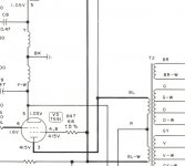
When I first looked at this schematic it appeared to be a direct lift of a McIntosh Unity Coupled Circuit, not surprising since it is. For a time McIntosh built amplifiers for Westrex under some kind of contract. In the data I was able to pull up there is a comment implying the circuit is very similar to a McIntosh MC225. There is a clean copy of the schematic, the OPT cathode winding is identified by the letters Y & Y-W.
This connexion provides negative voltage FB. The stage gain is reduced by ~14db. The Damping Factor ends up about 3 or 4, before any full loop FB is applied.
If there were simply inductances on the cathodes, that would apply negative current FB , the gain would decrease but the Damping Factor would be low or non-existent. Norman Crowhurst gives an excellent account of how the circuit works.🙂
Attachments

This paper?
https://mennovanderveen.nl/cms/imag.../publicaties/Schade_1938_Beam_Power_Tubes.pdf
I don't see all those statements. Am I missing something?
I did find "250V to 300V". Followed by "a wide range".
I do not see that the screen has to be 15V or 15-20V down.
Page 338, 343 & 352.
AM
Forgot to attach something I found years ago. Although the article concerns triode use of a tetrode/pentode it even more so affects UL operation since the output transformer has a greater voltage drop for the plate than for the screen. Modelling seems to support this. I found it helpfull with keeping plate dissipation under control when B+ is outside the expected voltage range after rectification (in spite of modelling).
Attachments
Last edited:
- Home
- Amplifiers
- Tubes / Valves
- New 7591A Amp Design, 35W x2