No, spend the time to look at the sample chart in the article. The article teaches how to convert to decibels as well. Then you will come to understand why ALL normal stereo potentiometers will mistrack. Look at the small values at the start. These small values have to be maintained by BOTH channels in a continuous variable resistor. Look at the first 5 or so values and then look at the total resistance of the whole rotation and then calculate the sensitivity and then convert to decibels. That is the reason why Tom recommends staying away from the first part of the rotation of the pot because mistracking between channels is severe at the early part of the pot as explained prior.
Conversely, if you were to have one channel's first say 4 resistors mistrack by a factor of two, by the time you reach the second to last resistor, you'd never notice it but at the lower levels it would be horrible.
Take an audio taper pot and an ohmmeter and take some measurements! Then stick in those values on a scientific calculator or in excel and you will see the problem. All reasonably priced pots suffer this unless you are super lucky!
Now if you are operating at the far end of the pot, yes, you are OK but if you increase your gain, you will be operating at the lower end of the pot and you likely will notice it as Tom explained.
Right. But as I also point out in the interview, it's actually really hard to find the spots on the pot with high tracking error. I was only able to do so because I deduced where the transitions would be from the data sheet and searched around those areas.
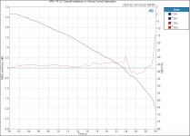
I'm not denying that you can find volume settings with a large (±2 dB in case of the Alps RK271, for example) mismatch, but you will only see that large mismatch over a minuscule change in pot rotation. We're talking a small fraction of a degree here. In actual use, you'll never see it, as evidenced by attached plot. The plot shows the attenuation vs pot rotation for my TCA HPA-1 headphone amp. It uses an Alps RK271 ("Blue Velvet") pot.
Contrast that with an attenuator, where finding a spot that delivers an SPL that's comfortable for background music can be a challenge.
I'm content with the tracking error of a volume pot. But, sure. For the ultimate precision in tracking you need an attenuator. If I ever design one, I would make it a relay-based one, though. Using one of the many volume control chips would be an option too. Those are basically attenuators in IC form.
Tom
Attachments
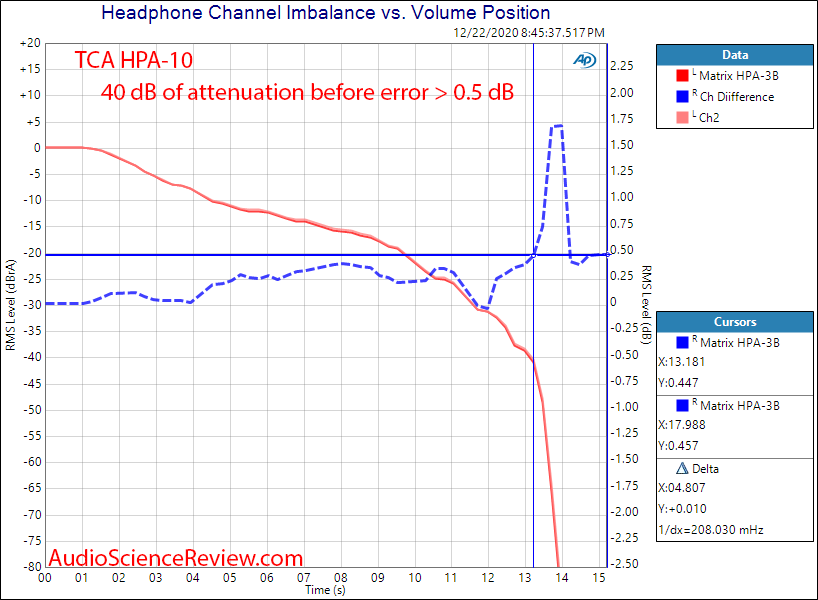
And here's the same plot for the TCA HPA-10 headphone amp. It uses the Alps RK097 pot. The RK097 is ~1/8th the cost of the RK271, so it does have a bit worse channel tracking. It's still a very good pot, though.
You can read ASR's review here: Tom Christiansen Audio HPA-10 Review (Headphone Amp) | Audio Science Review (ASR) Forum
Tom
You can read ASR's review here: Tom Christiansen Audio HPA-10 Review (Headphone Amp) | Audio Science Review (ASR) Forum
Tom
Last edited:
Using one of the many volume control chips would be an option too. Those are basically attenuators in IC form.
Tom
Hello Tom
I know a little about electronics but I am no expert.
I was surprised that those volume control chips are not used more often. I guess with these chips there is no problem with equal volume control even with 4 and more channels. Or not?
I guess it also makes it a lot easier to add a remote control to control those chips.
I.e. as far as I see you also don't use them in your volume control products. Why not?
The volume control ICs that are affordable are not all that great. The PGA2320 is decent and affordable, but with 17.5 uV RMS noise and 0.001% THD+N it'll be the dominant source of both noise and THD+N when used with my Modulus amps.
The ones that are good are expensive. Like $20/each @ QTY 100 expensive. That means I'm putting several $k of ICs on boards and sticking the boards in my basement hoping they'll sell.
Tom
The ones that are good are expensive. Like $20/each @ QTY 100 expensive. That means I'm putting several $k of ICs on boards and sticking the boards in my basement hoping they'll sell.
Tom
Can you name one or more of those good and expensive ICs please?
I understand that it doesn't make sense for you to keep a rail of those in your basement. But maybe I can afford a few of them in my living room. 😉
I understand that it doesn't make sense for you to keep a rail of those in your basement. But maybe I can afford a few of them in my living room. 😉
Can you name one or more of those good and expensive ICs please?
Cirrus Logic has a couple. The JRC MUSES one seems popular as well.
Tom
MSB Technology had a volume control box some time ago that used Analog Devices multiplying DACs - they're not known for low-performance products. There's a chip that Nelson Pass has used in some Pass Labs products. ADI also has a number of what they call 'digital potentiometers' that they advertise for use as audio volume controls. There are a number of chips out there; just search the web sites of analog IC manufacturers.
Many moons ago one of the Danish hifi/electronics magazines (probably High Fidelity) had a DIY preamp project called 'Air' where they used a multiplying DAC for the volume control. This was probably in the early 1990s. I seem to recall that they used a Burr-Brown MDAC.
ADI has a good writeup on the topic here:
New High-Resolution Multiplying DACs Excel at Handling AC Signals | Analog Devices
Tom
ADI has a good writeup on the topic here:
New High-Resolution Multiplying DACs Excel at Handling AC Signals | Analog Devices
Tom
Last edited:
Hello Tom,
I am looking for an amp to build/buy that can drive Audeze planar magnetics. Which of your various Neo or TCH amps would be best? Any mods you'd make to them to do the job best?
I am looking for an amp to build/buy that can drive Audeze planar magnetics. Which of your various Neo or TCH amps would be best? Any mods you'd make to them to do the job best?
Ok, Seems either this amp or the HP-2 is suitable to drive my Audeze planars. My new question is can I double this amp+EVM to create a balanced output headamp with twice the power?
The HP-2 can provide higher output current, so that would be better suited for the lower impedance phones. That said, the planar headphones are rather inefficient so the higher output swing and higher output current of the TCA HPA-1 could be beneficial, especially if you like to crank it loud.
Bridging the HP-2 or HP-22 is not such a hot idea. You need an output stage that can push a few ampere for that to work well.
Tom
Bridging the HP-2 or HP-22 is not such a hot idea. You need an output stage that can push a few ampere for that to work well.
Tom
Thanks Tom,
I ordered one of the hp-22 boards just now. I will order an EVM soon. The Audeze I will be driving is the lcd-i4. I think this will work fine. The i4 is a 32 ohm planar but also fairly efficient and easy to drive. So I was thinking of buying 2 boards/EVMs and using each pair to drive 1/2 or a differential or balanced signal?? I'm just going to try one pair for now as I don't even know if that would work?
I ordered one of the hp-22 boards just now. I will order an EVM soon. The Audeze I will be driving is the lcd-i4. I think this will work fine. The i4 is a 32 ohm planar but also fairly efficient and easy to drive. So I was thinking of buying 2 boards/EVMs and using each pair to drive 1/2 or a differential or balanced signal?? I'm just going to try one pair for now as I don't even know if that would work?
Oh yeah, I read the reviews of your HPA-1 amp. That is how I ended up here, along with your power amps.
Sure. You'd have to make an SOIC-DIP adapter for it, but it'll work just fine. The DIP-ADAPTER-EVM from TI is your friend there.
Tom
Tom
Tom, Thanks!
Hickup with mouser:
if C5,C3 22uF/25V Nichicon UES1E220MEM 647-UES1E220MEM are out of stock
should I use: 35volts, 10uF of the same series?
BTW, Elna Silmic mouser#555-RFS25V220MF3#5
plenty of these in stock.
Good alternative?
Final question: I'd like to move the headphone jack to somewhere a bit further from the volume knob. Recommended method?
Last edited:
647-UES1E220MEM1TD works. It's the exact same cap. Just in ammopack instead of bulk.
I'd use short wires. I write a bit about that in the design doc.
Tom
Final question: I'd like to move the headphone jack to somewhere a bit further from the volume knob. Recommended method?
I'd use short wires. I write a bit about that in the design doc.
Tom

- Home
- Vendor's Bazaar
- Neurochrome HP-22: A high-performance DIY headphone amp for less than $100