TBH I am not entirely sure why it soldering not ideal but I have read some other thread online saying the socket may melt while soldering. If soldering is possible, it make my life a lot easier. Thank you. i am using iec cable from power supply so they come with fuse holder, I may find other IEC socket with similar spec with PF0001/28 you suggested since my goal is to find a enclosure as small as possible so that it can be a better replacement of my O2 amp (comparable in size and better sound quality)!
TBH I am not entirely sure why it soldering not ideal but I have read some other thread online saying the socket may melt while soldering. If soldering is possible, it make my life a lot easier.
Soldering shouldn't be a problem if you have a decent soldering iron or soldering station and you know how to use them.
With relative high temperature and a relative big tip you have to heat the contacts maybe only for a second, put solder on it, and it's done.
If you use a small tip or a bad iron then you have to heat it up for a long time and then the whole assembly gets too hot.
Many passive and active parts can handle high temperature - but just for a short moment.
I use 600-700 ºF (315-370 ºC) for soldering with leaded solder. I generally find that a larger tip (higher contact area) works better than just cranking up the temperature on stubborn solder joints.
For lead-free solder, I'd probably up the temperature to 700-800 ºF (370-425 ºC).
Tom
For lead-free solder, I'd probably up the temperature to 700-800 ºF (370-425 ºC).
Tom
Hello All,
I went to Mouser.com to order the parts list for the project.
The 3 pin version of the J1 and J3 were out of stock. I went to the cut sheet and found the part number for the seven pin version and ordered that one. Now with a pair of diagonal plyers i will snip the thing right down the center of the middle pin. With the help of a 8 inch mill file there will be two perfectly fine 3-pins for J1 and J3.
For your soldering tool a larger tip will heat things up to melting temperature a lot faster than a smaller tip with a higher temperature. A little dab of solder on the tool tip will help heat/speed things up as well.
Thanks DT
In Appendix A-1 I provide an alternate part for the 2-pin and 3-pin header connectors. Cutting a larger connector to size works too, though.
Tom
Tom
I think I checked all relevant headers which I could find on the Mouser page. I tried to find matching headers for 2pin and 3pin. And the headers had to be higher than 5mm which is the height of the headphone connector and higher than the pins on the TI board. I didn't find any matching headers. So I also ordered headers with more pins.
When they arrive I will check if I will cut them to the correct amount of pins. Or maybe I just remove the pin part which is soldered into the PCB and leave all sockets.
My delivery from Mouser is from the USA. I don't know where else they have warehouses so what I wrote above might be different depending on your location.
Mouser part number 437-8018700310001101 listed in the appendix is out of stock too.
Argh! Gotta love the just-in-time management of inventory. Especially when lead times grow due to "external events".
Tom
Hello,
The mouser parts package is due today.
I will post some test results in a day or two.
Thanks DT
The mouser parts package is due today.
I will post some test results in a day or two.
Thanks DT
I've been listening to a breadboarded version of the HP22 with a slightly different input filter to the actual board for some weeks now. I have to say I'm already very happy with the results, even with this lash up, particularly into Sennheiser HD650's.
Thank you Tom.
https://www.diyaudio.com/forums/attachment.php?attachmentid=914492&stc=1&d=1611433673
I have experimented with different supplies, starting from a raw supply with just some CRC filtering, and subsequently trying LT 3045/3094 boards and through to super-regs and choke filtering. I have to say this path of ever more complex supplies doesn't make a lot of difference if you are using high impedance headphones IMHO but it does have a noticable effect on my 32ohm Grado SR325's. I do find the Grado's almost unbearable to listen to with the higher impedance/lower line rejection supplies, but that fatigue reduces with the LT supplies and is no longer present to me with the Super-regs.
With the super-regs the breadboarded HP22 is on a par with my HP2.
Anyway I've just completed the real HP22 and will be trying it in the next few days. If I find similar issues when driving my Grado's then I will try to capture hard evidence of any possible cause and post it here.
https://www.diyaudio.com/forums/attachment.php?attachmentid=914493&stc=1&d=1611433673
John
Attachments
Last edited:
I have to say this path of ever more complex supplies doesn't make a lot of difference if you are using high impedance headphones IMHO but it does have a noticable effect on my 32ohm Grado SR325's. I do find the Grado's almost unbearable to listen to with the higher impedance/lower line rejection supplies, but that fatigue reduces with the LT supplies and is no longer present to me with the Super-regs.
In that case, you will like the Neurochrome Preamp Power Supply as well.
Tom
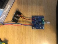
I just received a BIG box from Mouser with all the parts. It's amazing how they pack a few small parts. I hope next weekend I will have time to put things together.
The small black box (bought locally in Thailand) should be big enough for everything. I will report about my progress.

The small black box (bought locally in Thailand) should be big enough for everything. I will report about my progress.
About the headers and no headers in stock:
I bought the headers from Tom's list but with 6 pins.
It's easy to cut them in the middle to have 2 x 3 pins.
I bought the headers from Tom's list but with 6 pins.
It's easy to cut them in the middle to have 2 x 3 pins.
Today I soldered the parts to the PCB.
One thing which Tom does not mention in his otherwise excellent documentation is that we should be careful to place the ferrite beads in the exact location where they should be.
If they are too much to the side, which is easily possible, then it is difficult to later solder the jumper to the board.
Here is the critical area.
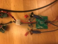
I just finished soldering everything together and it works. 😉
The picture contains all parts. The connections are temporary, and I have to put everything in the small box. I know already it will fit but I need some precision tools before I put things together.
I used separate RCA connectors to fit my box.
For the power supply I used 2 x 3 x 16340 rechargeable lithium batteries. I will charge them with a RC hobby charger which I have already. I chose the 16340 because they are relatively small and powerful enough.
I followed Tom’s excellent documentation, and all works as expected.
Here are my first impressions
The HP-22 sounds very good, and the maximum volume is high.
My first test was with my mobile phone and my SONY MDR-F1 headphones.
When I switch the amp on or off then I hear a switching noise. But this is low volume even if the potentiometer is set to max.
Tom suggests a test procedure with a test tone in his description. I did what he suggested but my phone is not able to output a signal with the suggested amplitude. I will not only use this amp with my phone but I will also use it with my phone and I want more than enough volume. For that reason I will increase the gain a little. Tom also describes this in his documentation. It is only necessary to change two resistors.
That’s my first impression. I can definitely recommend this little amp. Thanks Tom.
Very cool. I'm glad you like the li'l amp.
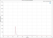
About the turn on/off transient: It's pretty small but, as you point out, it's not zero. I did the best I could given that I didn't want an output relay for cost and size reasons. I did test it with a pair of sensitive IEMs and didn't find the pop to be objectionable.
Unlike other manufacturers I actually characterize this. See attached measurement.
I'm looking forward to seeing the completed build.
Tom
Attachments
A question for Tom: I plan to change the resistors on the HP-22 to have a higher gain. (reason: see above)
One option is that I try resistors according to your table until I think the amp is loud enough for me.
But what happens if I set the gain too high?
Let's say I change the gain from the standard 10dB to 20dB.
I guess if my input signal is not too high then all is fine.
But what happens if (by accident) the input signal is a little too high? Would that likely result in a horrible noise in my ears and possible destruction of my ears or headphone?
It is better that I increase the gain only a little if I need only a little more gain?
I don't really care if I have only 1/2 turn of the potentiometer to set the volume to what I want. That is accurate enough for me.
Thanks
Let's say I change the gain from the standard 10dB to 20dB.
I guess if my input signal is not too high then all is fine.
But what happens if (by accident) the input signal is a little too high? Would that likely result in a horrible noise in my ears and possible destruction of my ears or headphone?
Well... If you crank the volume to the max with 20 dB gain, the amp will clip. This can be pretty hard on your headphones. But if you keep the volume turned down, all will be well.
Do note that the RK097 potentiometer does have worse channel imbalance at volume settings below -40 dB (so around 8-8.30 o'clock). That will be the limiting factor as far as performance goes.
I wouldn't go much higher than 12-16 dB of gain. I usually use unity gain.
Tom
OK, for those who find the mistracking a bother, this used to happen to me in the late 70s until I was introduced to something like this....a switched attenuator. There are better ways to do this now but this article changed my use of potentiometers forever since 1980.
I still have three of them and actually still using one I built in summer 1980. ( I had just graduated UBC and came to Toronto to work and I found Toronto to be a mecca for parts relative to Vancouver!)
https://leachlegacy.ece.gatech.edu/papers/stepatten/stepatten.pdf
With a spreadsheets the construction of a custom taper is easily accomplished and now 1% MF resistors are commonplace. One should consider something like this if they are able to live within the 23 positions. What I also did once was to wire a DPDT switch in to that I could have a low listening range and a higher listening range and still tweak steps within 1 or less dB. The idea of a customized taper as shown by Leach is sound as most constant stepped attenuators waste too many steps at the low range.
BTW rotary switches are now pricey but NOS can be found on Ebay.
Also, Tom, I remember during one of the interviews you were asked about the "Audio" publication. Well the above article hails from that publication so I imagine you now have an idea of what the Audio magazine was about. It was that magazine that got me into DIY actually.
Last edited:
OK, for those who find the mistracking a bother, this used to happen to me in the late 70s until I was introduced to something like this....a switched attenuator. There are better ways to do this now but this article changed my use of potentiometers forever since 1980.
I still have three of them and actually still using one I built in summer 1980. ( I had just graduated UBC and came to Toronto to work and I found Toronto to be a mecca for parts relative to Vancouver!)
https://leachlegacy.ece.gatech.edu/papers/stepatten/stepatten.pdf
With a spreadsheets the construction of a custom taper is easily accomplished and now 1% MF resistors are commonplace. One should consider something like this if they are able to live within the 23 positions. What I also did once was to wire a DPDT switch in to that I could have a low listening range and a higher listening range and still tweak steps within 1 or less dB. The idea of a customized taper as shown by Leach is sound as most constant stepped attenuators waste too many steps at the low range.
BTW rotary switches are now pricey but NOS can be found on Ebay.
Also, Tom, I remember during one of the interviews you were asked about the "Audio" publication. Well the above article hails from that publication so I imagine you now have an idea of what the Audio magazine was about. It was that magazine that got me into DIY actually.
I that not a solution in search of a problem?
The potentiometer works just fine.
- Home
- Vendor's Bazaar
- Neurochrome HP-22: A high-performance DIY headphone amp for less than $100