Although this seems like a deep center field plan for ordinary feedback, it can be the basis of an overload management scheme by sharpening the go/no-go curve, in parallel with ordinary, non-overload feedback. Above the overload threshold, gain could be squashed, minimizing overload artifacts.
All good fortune,
Chris
All good fortune,
Chris
Attachments
Thanks Chris for this interesting point of view that I totally missed.it can be the basis of an overload management scheme by sharpening the go/no-go curve, in parallel with ordinary, non-overload feedback. Above the overload threshold, gain could be squashed, minimizing overload artifacts.
Would a simple optocoupler with the led across the screen resistor piloting a voltage divider at the input of the amp be simpler and more effective?
Thank you smoking-amp for your feedback on the topic, also on how to represent the data. Really appreciated.
I will study it and revert here.
Looking at the diagrams in your post 14, I've just realized that it is -NOT- the same as Hawksford Error Correction, due to a small detail.
The Hawksford Error Correction scheme takes the reference signal for Op Amp B, the - input, from a summer of actual input and the derived error correction. While post 14 is using the actual input for Op Amp B's reference.
This avoids the positive Fdbk loop, but then becomes conventional N Fdbk with gain enhancement (over the power Amp part) N Fdbk. Which should be more stable.
The Hawksford scheme is generally only used for a local high BW correction of the output stage (for SS typically), since it is VERY sensitive to phase shifts with the positive Fdbk loop contained in it.
The gain enhanced version (post 14) might be stable enough to operate through the OT, but is only really needed if the Amplifier itself does not have enough gain already to reach maximum possible global N Fdbk.
( The linked P-P tube Hawksford style scheme operates from the primary side of the OT to avoid most phase shift. )
------------------------------
In agreement with JXDKing about global N Fdbk being the most effective for a given usable gain, with the extra gain getting burned off in local loops, particularly at HF where phase shift is worst globally.
But there is the possibility of using local N Fdbks with finite gains to complement each other, if one loop tends to have complementary distortion properties to another. (although one will have to search extensively to find any such cancellations) This sort of thing gets done in SS Op Amps using extensive mathematical modeling, probably hopeless for a tube Amp with all its tube variation factors. But DIY tube amp constructors have the option of adjusting the loop factors individually to at least improve performance some.
One important case of this is the recent UnSET/CED/ "new" series Schade schemes. The Mosfet/cathode drive effectively varies the screen V and the plate V by the drive V. This allows one to compress triode curves at high V to remove curve "rollover" effects. An optimal Fdbk gain factor, and/or % variation of screen V factor can be used to straighten up the triode curve "rollover". This effectively is a pre-distortion effect that matches up well with a common tube distortion. (along with the linear N Fdbk operation alongside)
Last edited:
I've asked to Arnaud (he has 15 years of experience on this kind of nfb) if applying this kind of feedback from primary side of the OTP wouldn't have been better, but he told me it is better from secondary taps. IMD on those tests stays at -72dB.
Would a simple optocoupler with the led across the screen resistor piloting a voltage divider at the input of the amp be simpler and more effective?
Sounds good, and an even more sensitive overload detector would be a comparator, much like your circuit, with a sharp knee, or threshold of difference between input and (scaled) output voltage, and an optocoupler squashing the input signal as you've proposed. McIntosh did this in semi-con amps in the 1970s and it can work really well.
ps: note: this is not "feedback".
All good fortune,
Chris
Last edited:
Arnaud's scheme depends on Op Amp B being linear to begin with. An actual Op Amp with a local N Fdbk would be a practical linear gain. Using tubes in an LTP stage would be more challenged there. But at least the signals and load are small at that point.
If it can work from after the OT without oscillating, then one has made significant progress. However, the simple phase shift fix, I suspect, is only going to work well in the audio passband, and not up around the xfmr resonance.
If it can work from after the OT without oscillating, then one has made significant progress. However, the simple phase shift fix, I suspect, is only going to work well in the audio passband, and not up around the xfmr resonance.
As far as I've understood (Arnaud is very available to explain), gain B is considered very linear because the applied signal is very small (being only the error component and not the full input signal).
I've proposed to have a LND150 instead of a tube, but apparently everyone used triodes there.
Filters on both sides of the differential gain stage need to be taylored on the OPT, as I've been told. Indeed they are all around 300 kHz in that configuration.
I've proposed to have a LND150 instead of a tube, but apparently everyone used triodes there.
Filters on both sides of the differential gain stage need to be taylored on the OPT, as I've been told. Indeed they are all around 300 kHz in that configuration.
Looking at Arnaud's scheme some more, it seems there may be a bug in the scheme. Maybe.
The 1st pass thru the schematic looks like it would cancel all distortion (assuming the gain control is set correctly), but the second pass thru then has no distortion in the output, so the correction term disappears. So then the third pass thru has the distortion correction term reappear. Oscillating correction?
Or does it settle at half the distortion corrected? 1/2 corrected seems to settle to a stable signal loop.
Hmmm, this may be where the gain B comes into play. Stable error correction then settles at 1/(2B) error left in the output. It would seem that gain B needs to be big.
The Hawksford EC integrates up the error correction term, due to the positive Fdbk loop, so that it stays active. Effectively taking gain B up to infinity due to the critically adjusted pos. Fdbk. (and an oscillator if adjusted up a tiny bit too far.) So just a different way of getting a large gain B in the loop.
Last edited:
The gain control is set to have no signal on the other side of the PI when there's no distortion on the output.
This document (linked here below and attached to this post not to lose it) compares the two feedback typologies you mentioned (just found, need to read it):
https://cdn.shopify.com/s/files/1/0...tas_investigation_of_feed_back_techniques.pdf
This document (linked here below and attached to this post not to lose it) compares the two feedback typologies you mentioned (just found, need to read it):
https://cdn.shopify.com/s/files/1/0...tas_investigation_of_feed_back_techniques.pdf
Attachments
Last edited:
So quite similar. ODNF needs OP Amp gain, and Hawksfor EC needs accurate unity gain in positive Fdbk to get high gain.
It seems to me that one could make an in-between version. Put an integrator where B is at, and it integrates up a correction term until the Error Only Fdbk goes to zero. The integrated error term then only changes value when an error appears on the output. Essentially a Tracking Error Correction (using a small time constant, like 5 uSecs). uTEC
TEC would seem to be a part of standard PID control. Proportional, Integral, Derivative control. The proportional part is the amplifier itself. The integral part holds the current error correction term. The derivative part of PID is interesting, it looks at the variation of the error correction term and predicts the trend via a derivative. Keeping the error correction term tracking the signal with minimal error occurring.
All such schemes depend on some tiny output error occurring to guide the processing. (and so the need for large gain somewhere) One could get even further carried away with a 2nd derivative to predict the variation of the 1st derivative, and on and on. But accuracy requirements in the processing circuitry get more extreme with each new overlay, and sensitivity to noise eventually drives the whole thing wildly astray. But I could see adding the 1st derivative.
Some design thinking called for to do uPID with tubes.
Incidentally, a PID type control was what allowed class D amplifiers to eventually go Hi-Fi.
Last edited:
Thank you again smoking-amp.
Searching this topic in Japanese I've found this interesting link (here you can read it in english: Google Translate ).
Luxman has developed four generations of this ODNF feedback circuit.
It is described by Isao Shibasaki in the November 2000 issue of MJ magazine (can anyone find it?)
Searching this topic in Japanese I've found this interesting link (here you can read it in english: Google Translate ).
Luxman has developed four generations of this ODNF feedback circuit.
It is described by Isao Shibasaki in the November 2000 issue of MJ magazine (can anyone find it?)
zintolo,
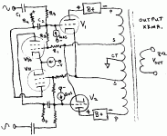
As I look at the schematic of Post # 14, what I see is:
1. The input signal is passed through the low pass filter, and from there to the parallel grids of the 12AX7.
2. The signal of the output transformer's secondary (with, or without, any distortion) from the rheostat and compensation cap, is applied to the parallel Cathodes of the 12AX7, by that RC network to the common cathode resistor.
3. The difference of the signal (1.), and signal (2.), is amplified by the parallel plates of the 12AX7, and that is applied through a coupling cap to one grid of the LTP 12AX7.
In my book, no matter how small or how large the amplified signal is from the output transformer's secondary signal, and no matter how little or how much distortion there is in that output transformer's secondary signal, the Sum of them are applied to the common cathodes.
That circuit is a negative feedback path; Right?
What may be unique about this amplifier, is the idea of designing the delay through the low pass filter to be the same as the delays through the amplifier tube stages and output transformer.
That is the only advantage I see of using all this extra circuitry, and quite possibly a very worthwhile advantage.
Right?
Last edited:
Before I forget this thought, I will write it here:
This kind of amplifier works best because the phase through the low pass filter, is equal to the phase through the whole amplifier.
That is all very well and good.
This scheme can be made next to perfect, as long as the load is a resistor.
The amplifier output tubes are operated as Pentodes, meaning that before negative feedback (or correctional feedback), the high plate resistance will apply current to the output primary, but with much less control on that primary versus UL mode or Triode wired mode.
. . . Then along comes a loudspeaker load that causes the amplifier's output phase to vary (it will vary until a correction feedback is applied to an earlier point in the amplifier circuit).
But now that means that the delay phase of the low pass filter, no longer matches the delay through the amplifier path.
The correction scheme now becomes less effective than it was when the load was a resistor.
Just my opinions.
Dear 6A3sUMMER,
the phase issue has been addressed here: Google Translate
The DF of the pentode configuration has been shown here compare to traditional GNFB: Transfo de sortie Supersonic W8 en correction differentielle - 6bm8-lab.fr
...but without going that far, our friends at solid-state section... ODNF or no GNFB power amp
the phase issue has been addressed here: Google Translate
The DF of the pentode configuration has been shown here compare to traditional GNFB: Transfo de sortie Supersonic W8 en correction differentielle - 6bm8-lab.fr
Other figures comparing the corr. Diff. to the traditional CR, those of the dynamic impedance at the output and therefore of the damping:
corr. Diff. : 0.43 ohm, damping = 18
CR trad. : 2.8 ohms, damping = 3 (CR rate = 15dB)
...but without going that far, our friends at solid-state section... ODNF or no GNFB power amp
zintolo,
I am looking forward to your report of the results when you build the amplifier as per the schematic in Post # 14.
Of particular interest to me is what output transformer you use.
Tests:
First into a resistor.
Second into a loudspeaker (please list the model).
Third, into a different loudspeaker model (please list the model).
Use at least one speaker that is a very difficult load.
For the tests with the loudspeakers, you can use the 'Denon Audio Technical CD', or something similar.
It has a single clock time impulse at a low repetition rate (and of course is digitally filtered), and tone bursts, at low repetition rates.
That keeps from burning out the loudspeaker drivers, because the time integrated rms power is low.
Solid state output circuits are one thing.
Vacuum tube output transformers are another thing.
I believe getting it right will certainly be recognized as a real victory.
Last edited:
Thanks 6A3sUMMER
I’ll let you perform the tests and get the victory, if you already have all the needed.
I’ll let you perform the tests and get the victory, if you already have all the needed.
- Home
- Amplifiers
- Tubes / Valves
- Nested feedback: best practices (Baby Huey and beyond)