I don't think you have both positive and negative DC on the sub speaker terminals. They are both positive 30v.
If you look at the positive and negative sub channel outputs with the scope, do you see the same signal?
Which was correct on the scope, the 70Hz or the carrier frequency on the speaker terminals? I'm assuming that the scope was wrong reading 70Hz because that would made the channel unusable.
If you look at the positive and negative sub channel outputs with the scope, do you see the same signal?
Which was correct on the scope, the 70Hz or the carrier frequency on the speaker terminals? I'm assuming that the scope was wrong reading 70Hz because that would made the channel unusable.
I did notice that the frequency reads 70hz on the scope screen. All of the previous screen shots with the shorted inductors either installed or removed also read similarly, between 68-71hz.
Should there be a different frequency displayed, or no frequency displayed?
I think the signal was very similar on both + and - terminals, I will go and check shortly.
Should there be + voltage on the + terminals, and - voltage on the negative terminals?
Should there be a different frequency displayed, or no frequency displayed?
I think the signal was very similar on both + and - terminals, I will go and check shortly.
Should there be + voltage on the + terminals, and - voltage on the negative terminals?
If they are both +, does that mean that one inductor is working and the other is not? Or is that issue coming from somewhere else and has nothing to do with inductors?
If I swap the inductor positions and then see only - 30v on both + and - terminals, then that would be a yes?
If I swap the inductor positions and then see only - 30v on both + and - terminals, then that would be a yes?
The subwoofer channel has only positive rail voltage. You can't have negative voltage on the sub channel terminals.
The output from the sub channel should have no measurable AC or pulsed DC (should be straight DC at approximately 30v).
You can't 'think'. Was it or wasn't it?
The output from the sub channel should have no measurable AC or pulsed DC (should be straight DC at approximately 30v).
You can't 'think'. Was it or wasn't it?
Benchmark readings from a 500/1
I bought a 500/1 v2 to help troubleshoot by having a working reference, and to become familiar with the circuitry since schematics are not to be found. I can see what the scope reading should be after testing the 500/1 outputs. It is a flat line with very little + and - voltage fluctuation. My USB scope shows average voltage also and it reads close to 0 with no signal and amplifier idling.
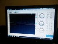
New Scope Readings of 500/5
I went back to the 500/5 and did some more teching. I ended up replacing all four IRF540 outputs with new ones since one of them showed a lower reading than the other three when 'turned on'. Since replacing those, the +30v average that was shown on previous scope shots has gone down to +/- 0v. It is still a wave that fluctuates between +13v and -12v, and not a flat line, but the average is 0.480v. It still shows a frequency of approximately 70hz.
I will post a pic of the current scope shot of the sub channel.
I bought a 500/1 v2 to help troubleshoot by having a working reference, and to become familiar with the circuitry since schematics are not to be found. I can see what the scope reading should be after testing the 500/1 outputs. It is a flat line with very little + and - voltage fluctuation. My USB scope shows average voltage also and it reads close to 0 with no signal and amplifier idling.
New Scope Readings of 500/5
I went back to the 500/5 and did some more teching. I ended up replacing all four IRF540 outputs with new ones since one of them showed a lower reading than the other three when 'turned on'. Since replacing those, the +30v average that was shown on previous scope shots has gone down to +/- 0v. It is still a wave that fluctuates between +13v and -12v, and not a flat line, but the average is 0.480v. It still shows a frequency of approximately 70hz.
I will post a pic of the current scope shot of the sub channel.

No, I don't have a dummy load resistor, but I can purchase the necessary parts tomorrow and build one. What would I do and look for once I have one?
Oops, I switched back to DC coupling and the scope readings are identical to those before. +30v, fluctuating between +45 and +16v.
Oops, I switched back to DC coupling and the scope readings are identical to those before. +30v, fluctuating between +45 and +16v.
You wanted to know if it was safe to connect a speaker to it. If you had a dummy load resistor (or a 2 ohm resistor used for current limiting), you could connect it to the sub channel. If it got hot and the amp drew more current with it connected (with no signal input), it would not be safe.
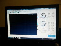
So I pulled the two inductors from the 500/1 and wired them up in the 500/5 just to see what two known good inductors would look like in this amp. I am seeing a flat line at 30v, but with no frequency displayed.
Is this a screen shot of a healthy sub channel that only needs the correct inductors?
I looked back at the screen shots I took of the 500/1, and I can see different frequencies displayed.
Is there supposed to be a frequency range displayed, or does it not make a difference?
Is this a screen shot of a healthy sub channel that only needs the correct inductors?
I looked back at the screen shots I took of the 500/1, and I can see different frequencies displayed.
Is there supposed to be a frequency range displayed, or does it not make a difference?
Attachments
Are you checking both the positive AND the negative speaker terminals?
They are both active. One would be passing signal through the 500/1 inductor and the other speaker terminal would have signal passing through the substitute.
Was the signal passing through the known-good inductor a straight line with either of the alternate inductors installed?
They are both active. One would be passing signal through the 500/1 inductor and the other speaker terminal would have signal passing through the substitute.
Was the signal passing through the known-good inductor a straight line with either of the alternate inductors installed?
So I tried something with these inductors. I got some insulated wire of the same gauge and I manually rewound both inductors myself. I figured that I had nothing to lose, and everything to gain. I did the known bad one first and installed it with the other original one and still had a wavy line on the scope. So I then removed the other and rewound that one also. I will post the scope screen shots of the sub channel + and -.
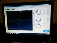
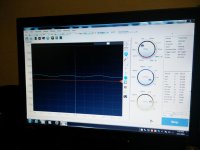
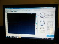
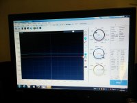
Scope readings
I now have a mostly straight line at 30v with a slight ripple to it, but nothing like the waviness from before. Not a straight line either but voltage fluctuation is from 28.5v-33.5v with an average of 30.7v on the + output. The - output has a very slightly less amount of fluctuation but the exact same average voltage of 30.7v. There still seems to be a frequency reading around 70hz but it fluctuates up and down a lot more. It dips as low as the 50s and 60s and peaks as high as the 100s, but always bounces back and forth around 70hz.
Speaker testing
I don't have a load resistor yet, but I connected a 4ohm 6x9 speaker to it and monitored the outputs with the scope. Nothing alarming, slight fluctuation in the average voltage down into the 20v range and up into the 30v range with the wave remaining exactly the same.
Supply voltage
I am using a battery for testing whichbis currently down to approximately 12.3v at rest, and approximately 12.0v with the amplifier idling. The Battery voltage doesn't not decrease with the speaker connected at idle with no signal. No decrease even when playing, unless a very bass heavy track is playing, even then only by .02v or so.
Monitoring heat
After 10 minutes of bench playing, the output transistors are just slightly warm, not hot. The inductors are more hot but I can put my fingers on them and it takes about 6-8 seconds before it becomes uncomfortable.
Questions
With these scope readings of the imperfect, slightly wavy sub output, does this look like a usable sub channel as is?
Should I attempt to rewind the inductors again to try to get the windings even tighter in an attempt to end up with a straighter line on the scope readings?
Am I wasting my time and should I just purchase known good inductors, with known accurate values?
Thanks.
Attachments
Last edited:
Put the amp back in the car with all 5 channels being used. Everything works like normal, everything sounds like normal. No protection lights, amplifier cool to the touch after 20 minutes of playing at 1/2 volume. No subwoofer voice coil burning smell like before, playing a 600w dual 2ohm sub wired to 4ohms. No unwanted frequencies audible from the subwoofer. Of course, I have not pushed it hard yet though.
Is it a ticking time bomb or can it survive long-term like this?
Is it a ticking time bomb or can it survive long-term like this?
- Status
- This old topic is closed. If you want to reopen this topic, contact a moderator using the "Report Post" button.
- Home
- General Interest
- Car Audio
- Need urgent help with JL 500/5 parts order