I have not yet been able to locate a person or facility locally that can test it for me, still trying.
Is the problem with the missing midrange frequencies related to the inductors?
I was hoping to at least get the midrange part of the amp totally repaired because I may need to shelf the amp until I repair or replace the inductors...
Is the problem with the missing midrange frequencies related to the inductors?
I was hoping to at least get the midrange part of the amp totally repaired because I may need to shelf the amp until I repair or replace the inductors...
The inductors for the sub channel have nothing to do with the rear channels.
You can probably test the inductors for basic function if you have a sine wave/function generator.
From an earlier post... There is more to an inductor than its value in micro/milli henries.
I don't know what could cause the loss of midrange frequencies. Sometimes a loss of ground will make a channel or pair of channels sound 'hollow' but not just the loss of mids. You'll have to trace the signal from the RCA inputs back to see where the signal becomes affected.
Glad to see someone else may be assisted by this post. Another update...
The inductors: I took them to an amp and speaker repair guy, but he did not have a (LCR) meter. His tech only looked at them, but said it is unlikely that they are causing my problem. I picked them back up so I could continue troubleshooting and will look for someone else if they are suspected again after more teching out...
The bass channel: I had replaced the two 220nj100 capacitors that come after the inductors with two .22uf 100v caps that I got from Digikey since I could not find anything 220 nano farad, only .22 micro farad. Are these the same or not? The outputs were heating up rapidly with the .22uf100vdc caps installed. I swapped those with the two 220nj100 caps that are on the preamp board so I would have the original caps in C527 and C531 and I also switched the positions that the inductors were in. The inductor that looks more heat-damaged gets warm at idle, while the less heat-damaged inductor gets uncomfortably hot at idle no matter which position they are in. The cap at C527 started to swell and bulge at the top. I then reinstalled the old caps that had vented at the top just to see if the amp would function since they were working before my ordered parts arrived. The bass section is currently playing and the outputs only get warm with this current arrangement. There is no excessive current draw since I am using a battery currently reading 12.3 volts off and 12.1 volts with the amplifier on. Nothing shorts or overheats and the amp idles continuously. Bass output is low, but the overall output of the amplifier is just as low.
Midrange channels: All IRF540s are in and clamped tightly to the heatsink. The zener diodes on all four channels read 3.8v and all driver boards act the same with the voltage rising properly with no over-voltage. I get output on all four channels. It appears that whatever part of the amplifier that is responsible for the band-pass frequencies is not functioning since the front channels only emit high frequency audio when the crossover switch is in the OFF or HP position, and emit nothing when in BP. The rear channels emit only high frequency audio. All switches and crossover pots have the appropriate effect when switched or turned with the exception of audio output on the front channels when in BP position. All audio seems to be rather low, but with the midrange frequencies missing it is difficult to tell.
Questions I have:
Are .22uf 100vdc capacitors the same as 220nj100 capacitors that are located at C527 and C531?
What would cause one output inductor to heat up more than the other? (Does that mean one is working properly while the other is slightly shorted?)
How do I find the cause of the missing band-pass frequencies? (Do I have to trace the path of the RCA center pin through the amplifier while inputting a midrange frequency until I find where it disappears?)
The rear and sub channels are on the same supply. The regulator for the rail voltage is connected to the sub rail. When you install the inductors, it changes the current draw from the sub rail and the regulator increases the duty cycle. This is likely why the rear rail voltage increases with the sub channel inductors in the circuit.
OK, another update...
I think the midrange section is in good working order. I decided to grab the iPod and run a track that I have with frequencies from 20-20k hz. To my surprise, all frequencies played loud and clear, so I then checked the preamp output of the deck. Apparently, the outputs are damaged. I am wondering if this amp did the damage since I experienced a damaged sub output on my Pioneer AVH-P8400BH last year, but couldn't figure out when and how it happened. But the four channels are currently playing loud and clear, and all voltages seem to be correct.
The sub channel is also playing loud and clear, however, the vented-top capacitors are still installed. The outputs do not heat up, but one inductor is getting hotter than the other. The amp is still apart as I want to do further testing before reassembling and installing it in a vehicle.
Current questions:
1) Is .22uf 100v capacitor the same as 220nj100 capacitor? (Outputs heat up with .22uf installed)
2) Can the preamp output of the deck be damaged by the amplifier rca inputs? (Not including accidental rca contact)
3) Is there any danger involved in leaving the vented-top capacitors installed after the inductors? (Think I remember a sub voice coil emitting a burning smell in the past while using this amplifier)
2) The other amp i suspect is a Directed 1100d5, is that amp capable of damaging the preamp outputs? Those were the amps in use at the time.
3) The .22uf caps are the same caps from question 1. These replaced the 220nj100 caps at C527 and C531, after the inductors. The vented caps must still be functional but I am not sure what effect this would have on a subwoofer while playing. If the inductors are filters, wouldn't compromised capacitors affect this filtration process?
3) The .22uf caps are the same caps from question 1. These replaced the 220nj100 caps at C527 and C531, after the inductors. The vented caps must still be functional but I am not sure what effect this would have on a subwoofer while playing. If the inductors are filters, wouldn't compromised capacitors affect this filtration process?
I don't know anything about that directed amp. If thew RCA shields read 0 ohms to the non-bridging speaker terminals for the corresponding channels, there are various faults that could chase damage to the RCA shield.
A 'vented' cap is generally an electrolytic capacitor that has had the electrolyte boiled and enough pressure formed to blow through the vents in the top of the capacitors. Film capacitors (like the 0.22uf caps) don't have electrolyte.
If the film caps show any signs of deformation from internal heating, they're likely defective. If they still cause problems when installed (as new caps), the inductors are likely defective and passing a significant amount of the square wave carrier to the speaker. This can destroy a speaker.
So, all signs point to defective inductors?
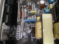
My problem is with C527 and C531. Whenever I install good caps in those positions, the outputs get hot, and the amp draws more current. With those removed, the outputs remain cool, and current draw is minimal. The better looking inductor gets uncomfortably hotter than the more heat affected one, so I assume that something is wrong with one, or both.
I have a USB scope that I never really got a chance to learn how to use since I figured out all these project amps without needing it, but I think I may need it on this one. I have scoped the output of the sub channel and will post some screen shots shortly. I don't fully understand what it is telling me, but hopefully I did it correctly and someone can identify what is going on in my sub channel.
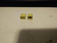
These are the "vented" caps I was referring to. I guess they could be separated inside because the amp plays bass even with them removed. They belong in C527 and C531 as pictured below. Do you know what their function is?
Attachments
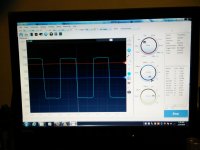
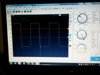
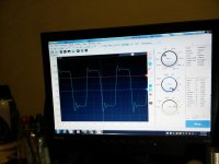
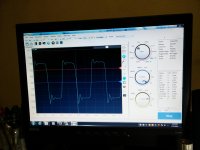
Below are the screen shots from scoping the sub channel. The settings are shown to the right of the screen. I believe it was 10v/div 4us. The dial is only numbered up to 5v but it still changed when rotated past 5v. The first two pics are without the caps installed, while the next two, in the next post, are with the .22uf caps installed in C527 and C531. Help please. Let me know if there is anything else I can do to ensure this amp doesn't fry subs. I will probably have someone rebuild those inductors if that will fix this amp...
Attachments
- Status
- This old topic is closed. If you want to reopen this topic, contact a moderator using the "Report Post" button.
- Home
- General Interest
- Car Audio
- Need urgent help with JL 500/5 parts order