Greetings, I have a JL Audio 500/5 amplifier that needs the two front channels repaired. Rear channels and Sub channel both work ok. I have all lights on all four driver boards but one for the front channel had a shorted 6.8v zener diode, if that is what it was. Both filter inductors look to have been very hot but the one for the front channels might have gotten too hot. I don't know if a replacement is available. This board is a REV 7. I have identified some of the obvious items that I need to order but can someone help me clarify what I already know and what I don't yet know. What else goes out on these when the front channels blow? Below are some of the items needed and their locations.
SURE ABOUT THESE
IRF540 (x4) Q202, Q203, Q102, Q104
47 ohm resistors (x2) R240, R140
NOT SO SURE ABOUT THESE (They're bad, but just not sure what they are) Can someone please tell me what is the proper description of the following parts if i am looking for them at Digikey or any other electronics parts retailer.
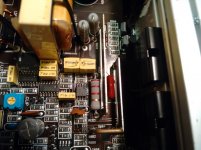
220nf100v box capacitors (x2) C527, C531
10nf100v box capacitor (x1) In between U657 and U653
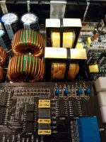
Filter Inductor (x1) L501
6.8v Zener Diode (x1) Vertical Driver Card for one front channel
SURE ABOUT THESE
IRF540 (x4) Q202, Q203, Q102, Q104
47 ohm resistors (x2) R240, R140
NOT SO SURE ABOUT THESE (They're bad, but just not sure what they are) Can someone please tell me what is the proper description of the following parts if i am looking for them at Digikey or any other electronics parts retailer.
220nf100v box capacitors (x2) C527, C531
10nf100v box capacitor (x1) In between U657 and U653
Filter Inductor (x1) L501
6.8v Zener Diode (x1) Vertical Driver Card for one front channel
Thanks for the quick reply Perry.
No, I don't have an inductance meter. I was thinking about swapping the one from the front in place of the rear one to see whether it works, but I am afraid of doing damage to the rear channels by doing this. Not sure if a shorted inductor is what killed the front channels. If I get everything else and can't get the inductor, I would feel safer trying the rear one in the front as that one is currently working with no issues. Would rather have 100wx2 fronts working than 25wx2 rears working.
The two 220nf100v capacitors have popped open on top and the 10nf100v capacitor got melted on top while removing the 220s. What is the function of the 220nf100v caps? I am assuming they have something to do with the front channel since the rears and sub are working with them removed...
As for the zener diode, I would rather not interfere with the working driver boards and just buy a replacement diode to fix the problem board.
MY NEXT QUESTIONS:
Based upon my identification of the obvious parts needing replacement, does it sound like these may be all that is needed to restore the front channels to functionality?
What size are the smd resistors and smd sender diode?
Is that inductor available for purchase anywhere besides JL Audio?
An externally hosted image should be here but it was not working when we last tested it.
An externally hosted image should be here but it was not working when we last tested it.
One inductor looks worse than the other, however not melted down like others I have seen.
So both inductors and both 220nf100v capacitors are part of the classD sub section only and have nothing at all to do with the front and rear channels?
Might the IRF540s, 47ohm resistors, and 6.8v zener diode be all that is needed to restore the front channels? Or is there something else I need to check before replacing those?
Could I use the components from the rear channels to repair the front channels?
Attachments
Went digging in this amp a little further as I need to order EVERYTHING I will need for this amp at one time. I have learned a little more from the replies on this thread so I went to measure rail voltage. Rear channels are steady with +16.4 and -16.4 but the front channels have +46 and -19.1. These readings were taken from the regulators (D800 + D801), through the vertical donut shaped coils(L801 + L802), through the rails and at the pads for the outputs(Q202 + Q203, Q102 + Q104). What is odd though is that I have -42.7 and +45.1 on the driver cards, specifically at the large 47k resistor on the left side, that I resoldered.
Could a bad SF1604GA be the reason my - rail voltage is so low, or would it be something upstream of that component?
I don't know if this actually means anything or not, but I placed the + probe on the B+ terminal and measured with the -probe and got these results. The outer legs of all four regulators measure 14.7v. The center legs of course differ from front to rear. D904 is -1.7 while D800 is -30.4, D905 is 31.2 while D801 is 33.6. Still trying to figure out if this tells me something or not.
Ok, so SF1604GA is a rectifier, not a regulator.
I swapped the - recruiters, front channel one with rear channel one. The front - rectifier still output only -19v while the + is outputting +46v. The rear channel rectifier remained a steady +16.4 and -16.4.
Is this rectified output determined by components before the rectifier or after the rectifier?
Would missing or damaged components downstream of the rectifiers cause the - rectifier to not produce full output?
If components before the rectifier is responsible for this problem, what do I check next?
The rear channels are fully populated with good outputs, resistors and driver cards while the front channels are devoid of output transistors, have blown resistors and missing the 6.8v diode on one of the driver cards. I guess I could lift the center leg of the rectifier to answer this question but don't want to keep removing and reinstalling rectifiers for fear of damaging their legs.
I have a USB scope that I got as a gift but have not fully acquainted myself with its use as yet. If you issue me some basic instructions as to what test to perform I may be able to use it.
Regarding the rectifiers though, I did actually lift the center legs of all four and it leads me to believe that all is well up to and before them. On the center legs for the front channels I got approximately -92v and +92v while the rear channels center legs put out approximately -38v and +38v. Each rectifier's voltage was roughly double what it normally should be when in circuit but more importantly, there seemed to be nothing pulling down the front channels - rectifier's voltage. When I reattached the center legs the -19v returned on the while the other three rectifiers resumed their normal outputs of +46, +16.4 and -16.4.
What could be pulling down the - rectifier's voltage. Could it be the missing 6.8v zener diode on the front left driver card? I know the voltages are different at the spot of that diode on both front channel driver cards, the left one with the missing diode is 3-4v while the right one with the diode is 8. something volts.
So I got the parts I ordered for this amp and installed them, but I still have some problems to resolve. I now have rail voltages of +/- 32.2 front and +/-16.6 rear going to the outputs. The green led is lit with no low ohm light.
The right front channel still has some repairs needed, and the output level of the amplifier seems to be very low, but especially the sub channel. I replaced the outputs of both front channels with IRF540PBF from Digikey, but the right front ones shorted out again, while the left ones are playing fine. I replaced the 6.8v zener diode on the driver board for the right and left front channels and a C3207 on the right front also. The left channel has identical readings as the left and right rear driver boards, but the right front has some different readings. On this board, the voltage on the 6.8v zener diode will jump to over 6v when the amp turns on, and then go down to 3.8v while the other three boards will just climb to 3.7-3.8v without exceeding that figure. I currently have the outputs(Q202, Q203) out of the amp for fear of burning up some more transistors.
The readings on the pads for Q202 and Q203 are (from left to right):
Q202: 3.22 32.2 0.0
Q203: -28.8 0.0 -32.2
The other problem I have is that the sub outputs (Q405,Q406, Q422, Q408) all get very hot quickly since I have replaced the 220nJ100 capacitors at C527 and C531. I could not find 220nf 100v capacitors and was told that .22uf 100v capacitors are the same thing, so that is what I ordered and used. If those capacitors are not in the amp, the outputs stay cool with no load, but heat up quickly when they are installed.
What can I check next to find the problems with this amp?
I had not turned any of the bias pots up to this time. I don't have any overheating problems with the midrange channels, only the sub channel. There are two pots in the sub channel, clip and offset. I turned the offset pot fully counterclockwise, like the Rockford amps, but the outputs still heat up with no signal or speakers connected. Fully counterclockwise causes the amp to emit a high pitched whine also, but the whine is not there if the pot is turned a little bit clockwise. It seems as if Q422 and Q408 are heating up more than Q405 and Q406. The only thing that stops the outputs from heating up is to remove the .22uf caps at C527 and C531 that I replaced. The 220nj100 caps that were originally there had busted open their tops. Do you think I have bad inductors?
The pots in the sub channel are not bias pots. The offset pot is used to set the offset across the speaker terminals to the lowest (closest to 0.000v) as possible). I'm not sure what the clip pot is for. In later amps, there was a pot to adjust over-current shutdown threshold but I don't think that's what the clip pot is for.
You could have bad inductors. Have you tried installing only one 0.22uf pot at a time to see which inductor is causing the problem?
You could have bad inductors. Have you tried installing only one 0.22uf pot at a time to see which inductor is causing the problem?
Are there any replacement inductors available for a 500/5 or does this require custom fabrication?
What's the specs on these inductors?
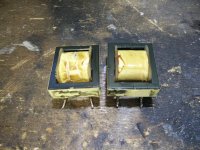
The driver board started to emit a high pitched whine as I was trying different test procedures so I eventually just removed the inductors. They both appear to be unhealthy but one is worse than the other. Doesn't really matter because if I have to replace one, I might as well renew them both.
Regarding the midrange section of the amp, I have a question:
The gate of Q202 jumps up to 6+volts before settling down to 3+volts. The other three channels simply rise from 0.1 to approximately 3.8volts without ever exceeding that. I already burnt up two IRF540 and do not wish to squander any more. What can I check to fix this?
What's the specs on these inductors?
The driver board started to emit a high pitched whine as I was trying different test procedures so I eventually just removed the inductors. They both appear to be unhealthy but one is worse than the other. Doesn't really matter because if I have to replace one, I might as well renew them both.
Regarding the midrange section of the amp, I have a question:
The gate of Q202 jumps up to 6+volts before settling down to 3+volts. The other three channels simply rise from 0.1 to approximately 3.8volts without ever exceeding that. I already burnt up two IRF540 and do not wish to squander any more. What can I check to fix this?
Attachments
Were the 540s tightly clamped to the heatsink when they failed?
If I read correctly, you stated that you had not adjusted the bias pots. That could be the problem.
The inductors are not readily available as far as I know.
Do you have an inductance meter to check them? I have 40uH in my notes for the value.
If I read correctly, you stated that you had not adjusted the bias pots. That could be the problem.
The inductors are not readily available as far as I know.
Do you have an inductance meter to check them? I have 40uH in my notes for the value.
I think the 540s failed due to a faulty C3207 on the driver board. I had to change one subsequently. The clamps were on them but not fully pressed down at the time. I was hoping to get the driver board to behave like the other three before reinstalling outputs.
Do the IRF540N work in this amp? I am asking because IRF540 is not locally available so was thinking to use 540N for testing and troubleshooting and then put in the 540s when I know all is well.
Would 6+ volts on the gate during start-up damage the outputs?
I plan to take the inductors to some electronics repair places to see if they can test it for me. If they are faulty, what are my options regarding this amp? Does it become a parts unit due to unavailable inductors ?
I don't know if the N version will work. I've had problems with the N versions in amps that originally had the 540N installed. I had to use the non-N version.
6v measured gate to source isn't a problem but it will make the FET conduct and if the other FET is also conducting, it could cause the FETs to fail. Having them tightly clamped down with heatsink compound and having a current limiter generally prevents destroying FETs.
You can sometimes rewind them if you can get the core halves apart without breaking them. It can be done if done carefully. Replacement cores can be sourced and wound if the originals can't be rewound.
This looks like the right core:
(search google for 00K3515E026.pdf)
Update, with new questions below...
So I removed the inductors and will be trying to find someone to measure them for me. With them removed, the sub outputs do not heat up. There is no low ohm light and the amp idles without burning up anything.
I also have put the outputs into the right front channel which has stopped the gate voltage from rising over 4v when turned on. It gradually climbs like the other three channels but has slightly higher voltage on the 6.8v zener diode than the other channels. Right front is 4.0v, left front is 3.8v, and both rears read 3.7v. All four channels play but there is a problem. The audio has frequencies missing, like the rear fill speakers in surround sound. The instruments play OK bit the voices are missing or echo-like sounding. Drums and guitars and such are clearly audible, but the singer's voice is either not audible at all or very, very low.
Can a generic 40uh inductor (from digikey or mouser) be used in this amp or is my only option to rewind these or to purchase two used ones from a parts amp?
Can I use ones with a different uh, like a 50uh from the JL 500/1, or a 30uh from a 1000/1?
What can I check to find out why my mids channels sound like they're playing in a coffee can?
- Status
- This old topic is closed. If you want to reopen this topic, contact a moderator using the "Report Post" button.
- Home
- General Interest
- Car Audio
- Need urgent help with JL 500/5 parts order