TSG,
Yeah, it was a whole boat load of fun finding out the peerless specs are pretty far off and that the sd was just plain incorrect on the PE website.
There's a thread I made alllll about it. Luckily some people helped me figure it out.
Yeah, it was a whole boat load of fun finding out the peerless specs are pretty far off and that the sd was just plain incorrect on the PE website.
There's a thread I made alllll about it. Luckily some people helped me figure it out.

10' rooms height ?The room isn't totally square but its basically a 14x18x10' room
Which distance are your rear wall ?
If Qts = 0.66 also might work quite well in an open baffle design.
I'm away from home for next 12-14 hours but will come back with both simulated room gain and a suggestion for cabinet design.
Last edited:
Just a tip - a good port design has a flare on both ends. The internal end is every bit as importiant as the extremal end.
Also the dimples will make it worse, just go smooth.
If you flare it gently over the full length you can make it shorter since the middle will be a little more narrow, but that doesn't reduce the output level ability so it's mostly win-win.
Also the dimples will make it worse, just go smooth.
If you flare it gently over the full length you can make it shorter since the middle will be a little more narrow, but that doesn't reduce the output level ability so it's mostly win-win.
The cabinet is already built and I'm not going to remake it so its really not worth wasting your time. Maybe you can help me with my next design though. I need to make something for my shop which is a very large space. Large enough to throw off all my low frequencies10' rooms height ?
Which distance are your rear wall ?
If Qts = 0.66 also might work quite well in an open baffle design.
I'm away from home for next 12-14 hours but will come back with both simulated room gain and a suggestion for cabinet design.
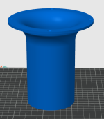
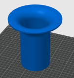
My ports have pretty extreme flares. With the advent of 3d printing I can make objects that wouldn't work so well with injection moulding.
Attachments
TSG,
I thickened the port walls and went to a 5" long 3" diameter. It did lower that 800 hz peak but thats about all it did. Thats actually probably worth it. Depends on if it chuffs at 3". The flare on the port is pretty extreme though
I thickened the port walls and went to a 5" long 3" diameter. It did lower that 800 hz peak but thats about all it did. Thats actually probably worth it. Depends on if it chuffs at 3". The flare on the port is pretty extreme though
Attachments
Last edited:
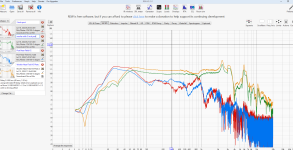
OK. I keep trying to zoom in on it to see if there are ny changes in the low end. The difference might only be 1 or 2db. A couple of things here:
1) I wouldn't worry much about the 800Hz thing because those frequencies should be well suppressed with your crossover.
2) How long is your 4" port? You might be better with it but it has to be as long as possible.
3) I will be home tonight and I can simulate this all in Basta and get a better idea of which port will do better for you.
Sorry to hijack, this graph shows again what I'm still trying to understand. Why doesn't the dip in woofer response line up with the peak of the port output?TSG,
I thickened the port walls and went to a 5" long 3" diameter. It did lower that 800 hz peak but thats about all it did. Thats actually probably worth it. Depends on if it chuffs at 3". The flare on the port is pretty extreme though
I didn’t read the whole thread and I’m no expert in designing bass reflex cabinets and the theory behind nor simulations but I had this driver some 15 years ago and my gut feeling reading this thread which may be of some value is as follows:
A) the box looks too big for this driver
B) I’m not sure this driver is intended for bass reflex nor multiway passive designs like this, I believe it’s a subwoofer primarily.
I would try to fill the cabinet with wool (pack it) and stuff the bass port with some foam just to see if you get any better response. That would hint to the direction you want to go. You would loose sensitivity but hopefully gain a slower roll off deep down.
I used mine in a ~25l sealed sub with great result but I had it active low passed at 80hz and high passed at 30 hz sub sonic filter. The whole sub box wood and all went smoking hot though which led me to understand I exceeded its purpose, but it was probably the amp that generated the most heat. It sounded great, it’s a nice driver for the money. Regret selling it.
OK.The cabinet is already built and I'm not going to remake it so its really not worth wasting your time. Maybe you can help me with my next design though. I need to make something for my shop which is a very large space. Large enough to throw off all my low frequencies
My ports have pretty extreme flares. With the advent of 3d printing I can make objects that wouldn't work so well with injection moulding.
Best you can do then is to make the cabinet sealed, because that 830667 is a very suitable driver for a 30 m2 room size.
Matches my target curve very closely when using the Qts = 0.56 data.
Reduce the volume to 30 liters if possible.
you should consider an internal flare as well to reduce resonance chuffing.The flare on the port is pretty extreme though
STV,
I can do that with the 3" but not with the 4"
Technically I can flare the entire thing. Just squeeze down at the center. I read a paper on this but it wasn't very good and didn't explain well enough how to set the length if the entire thing is flared
I can do that with the 3" but not with the 4"
Technically I can flare the entire thing. Just squeeze down at the center. I read a paper on this but it wasn't very good and didn't explain well enough how to set the length if the entire thing is flared
Yeah, I already saw this. I decided on the boost in bass from the port rather than the loss from the seal. At least this way I can decide how much I want to annoy my nieghbors. Just seal it or port. Its swappableOK.
Best you can do then is to make the cabinet sealed, because that 830667 is a very suitable driver for a 30 m2 room size.
Matches my target curve very closely when using the Qts = 0.56 data.
Reduce the volume to 30 liters if possible.
View attachment 1334458
OK. I apologize for generally leading you in the wrong direction when you have been on the correct path (mostly). All of my modeling with the wrong T/S parameters was problematic. According to Basta, which is a program I highly recommend, either port is going to give you the same result. Your measurements have confirmed this. It does say that this driver would do better with a smaller enclosure and as someone above recommended to stuff it, I think that's a good idea. If it were me, moving forward with this box and configuration, I would stuff it and design the crossover around what you have with the 4" port. Be careful with the stuffing blocking the port or being too close to the drivers. Otherwise, I think it's going to be fine. You will likely have an excess of low end so keeping these away from walls will be beneficial.The 4" port is 11" long
Will the crossover be passive or active?
A bit late to the discussion, but still…
I examined the picture of the system. Tallish enclosure with port down below. Such designs do not follow classical reflex calculations but rather behave as a MLTL. In which the (vertical) position of the woofer becomes an issue. The sheets of MJ King come to mind.
In general, a port so near to a cabinet wall will not follow theory anyway. The air spring cannot function 100 percent. That often won’t be a big issue, but one should not neglect it.
Jawen.I use it in 50 liter tuned at 30 hz.
This with HP 25 hz and LP at 150 hz, and have Faithal 5FE120 from 150 hz.
Real good quality bass in 50 liter reflex
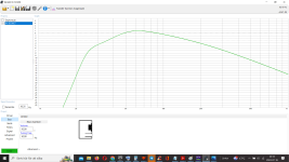
WinISD do not add for room gain, so the result you get is response in complete free field with no boundaries at all.
When putting that speaker into a room you need to add room gain because of reflection of floor, ceiling and walls.
So basically the result you get from WinISD do not represent the final result by it self.
Here an example of simulated room gain for a 30m2 room where speaker drivers are placed 60cm from rear wall, 80cm from side walls and 40 cm above the floor. Approx. Zero line is -2dB.
What you need to do is to add or subtract the dB you can read from this chart compared to the curve you get from WinISD to get
a better representation of what the final result will be when the speaker are placed into a room.
Of course everything is simulations, but that will get you in the right ball park at least.
830667 is very well suited to be used in a quite small closed box. It is designed for that purpouse.
They will be placed pretty close to the walls (wife decided, no other option). I can always plug the port hole and see how that does if we decide its too much bass. Kind of fun actually that we can swap between lots of bass or less bass with just a couple screws.OK. I apologize for generally leading you in the wrong direction when you have been on the correct path (mostly). All of my modeling with the wrong T/S parameters was problematic. According to Basta, which is a program I highly recommend, either port is going to give you the same result. Your measurements have confirmed this. It does say that this driver would do better with a smaller enclosure and as someone above recommended to stuff it, I think that's a good idea. If it were me, moving forward with this box and configuration, I would stuff it and design the crossover around what you have with the 4" port. Be careful with the stuffing blocking the port or being too close to the drivers. Otherwise, I think it's going to be fine. You will likely have an excess of low end so keeping these away from walls will be beneficial.
Will the crossover be passive or active?
I just did a quick simulation - just in case you want to try a filtered bass reflex alignment:Kind of fun actually that we can swap between lots of bass or less bass with just a couple screws.
1) Tune the helmholtz (bass reflex) resonance to about 25 Hz
2) include a series cap with ~2000 uF (eventually two polarized 4000 uF caps in series with negative leads connected).
grey: without cap, red: with cap

What's your method for combining these responses? Here's mine
1. Woofer nearfield. Centre on dustcap is important. Less than 10mm away
2. Same drive level as 1, measure port nearfield. Centre on port but don't breach the port entrance. About 5mm away is fine
3. Scale nearfield port to woofer. Use formula or eyeball the tails between 10 and 20 Hz. I prefer formula scaling
4. Apply baffle diffraction. Response to combined nearfield
5. Splice 4 with Fairfield woofer where there is good overlap. Usually this is somewhere between 300 and 700 Hz if you are using a standard room 4.5msec ( i.e 200hz ) gate
- Home
- Loudspeakers
- Multi-Way
- Need some help with my woofer and its port. Getting huge rise in deep bass out of this Peerless 8"