TSG,
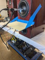
I am going to try to measure with with a plate blocking the port.
If that doesn't work I'll print a 3" port at 13" and see what happens
I am going to try to measure with with a plate blocking the port.
If that doesn't work I'll print a 3" port at 13" and see what happens
Yes, manually moving it was my second option. I just wanted to see if maybe I was doing something wrong. Could just be a glitchI see what you're talking about here and I'm not sure why it would do that. Is there some sort of offset baked into the summed response? Are the measurements out of polarity from each other? Maybe you could just manually move it up until it looks like it's in line where it should be (obviously that's not very scientific, but it could work). I would just use the near field woofer measurement to cross to the mid and ignore the port measurement. Don't worry about summing it with the port since the port is theoretically just dealing with frequencies well below the mid range driver.
Zero difference in response with a plate blocking the port. So I guess it isn't port interference
I can try a 3 inch port. I will model it and set up the print. I am also going to use a different filament type. The ASA has a sort of "ring" to it although it is very stiff. The PETG material is much more "dead" but is less stiff so I will have to make the sidewalls beefier
I can try a 3 inch port. I will model it and set up the print. I am also going to use a different filament type. The ASA has a sort of "ring" to it although it is very stiff. The PETG material is much more "dead" but is less stiff so I will have to make the sidewalls beefier
Attachments
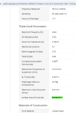
Just want to confirm before i go ahead and print new ports..... did you use the SD off of Parts Express for your calculations?A 4" port would be fine if it was 24" long. A 3" port should be about 13" and would fix the rise below 100Hz.
They have the wrong SD there. The SD from the Peerless website is 201. PE has it down as 213
Attachments

AFAIK, if your port and drivers are correct, your near field woofer output should dive around the port tuning frequency. You can check the port F by the right most resonant peak in the impedance curve. Here's a classic example from a Wilson Sasha review:

The blue line is the woofer nearfield measurement, and red is the port. So if you don't have this dip your port isn't working.
The first is that if I really want to include port and woofer near field I start by using a combined far field (1m or more) to gauge how much of a contribution the port it makes. IOW, I use the far field as the benchmark for what should be correct summing at the port frequency.
Alternative cheat is, if you are doing everything far field anyway, measure the woofer + port at far field. You'll have to eyeball around the bass modes but if you use gated measurements below the woofer/tweeter point you should be fine.

If the port walls are very thin, that might be an issue. But the overall shape of your port response seems kind of flat to me, with elevated higher frequencies farther up than I would expect. It's also relatively smooth up there, which you typically don't see in port resonances. This could be leakage out of the port due to nearness to the woofer. It could also be a measurement error.Is it possible it is too thin or it is flexing and that is causing the resonances we see in those higher frequencies
It's hard to judge things from a distance, but my advice would be to try to make sure you don't have measurement errors before printing new ports or doing any other significant modifications.
How is your gating/windowing set? To get good resolution at low frequencies, you need a really long window. Since the signal is so much higher than the background noise, long windows are OK in nearfield measurements.
Is there any damping in the bottom of the box? Above a few hundred hertz, acoustic foam is pretty efficient, so adding some of that between the port and woofer might help determine if high frequency leakage is one of the problems.
Yeah I misjudged by hole size so get true 4" the walls ended up 2.3mm thick. I'd like them more around 4 with PETG. Off the shelf ports are only 2mm thick so I thought I'd be fine.If the port walls are very thin, that might be an issue. But the overall shape of your port response seems kind of flat to me, with elevated higher frequencies farther up than I would expect. It's also relatively smooth up there, which you typically don't see in port resonances. This could be leakage out of the port due to nearness to the woofer. It could also be a measurement error.
It's hard to judge things from a distance, but my advice would be to try to make sure you don't have measurement errors before printing new ports or doing any other significant modifications.
How is your gating/windowing set? To get good resolution at low frequencies, you need a really long window. Since the signal is so much higher than the background noise, long windows are OK in nearfield measurements.
Is there any damping in the bottom of the box? Above 200 Hz or so, acoustic foam is pretty efficient, so adding some of that between the port and woofer might help determine if high frequency leakage is one of the problems.
I'm gating super far ahead for the near field. I'm just dragging the green R far to the right so I can see response down to 20 hz.
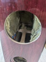
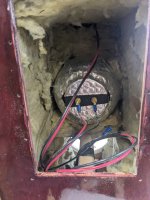
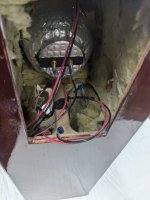
They is bunch of damping in the box. All the walls have R15 woold 2" thick and then the upper portion has some more stuffed around the mid enclosure and by the tweeter.
What do you mean by high frequency leakage? You mean the woofer measurement might be leaking into the port? I can take the port measurement again with the plate there and see if anything changes.
I will attach pics of the box stuffing
Attachments
That also winds up being the resolution of your measurement though. So, if you use a 50 millisecond long window, your lowest valid frequency and limit of resolution are both 20 Hz. That's not enough resolution to see some of this stuff. Try lengthening the window to 200 or 400 milliseconds and see if more detail shows up. Keep lengthening the window until no more low-frequency details develop.so I can see response down to 20 hz.
No, I mean the woofer back wave at higher frequencies coming out of the port. You want the port output at port/box volume resonance, but nothing else coming out of the port (optimally). In practice, some of the midrange can bounce around inside the box and leak out through the port. Including more absorption between the woofer and port might help (if that's a problem - I'm still not sure your measurements are showing everything that's going on).You mean the woofer measurement might be leaking into the port
Last edited:
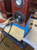
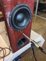
What is that on the backside of the driver?? (or is it the midrange?)
The Peerlees 830667 is a good driver . ( is it mounted tightly without airleaks? )
The Peerlees 830667 is a good driver . ( is it mounted tightly without airleaks? )
Last edited:
I think that's the midrange, with a 3D printed rear chamber on it. Related thread:backside of the driver
https://www.diyaudio.com/community/threads/3d-printed-mid-enclosure-should-i-stuff-it.413607/
Its a mid range with a 3d printed enclosure that is stuffed. Everything has closed cell foam laser cut gaskets. No leaks.What is that on the backside of the driver?? (or is it the midrange?)
The Peerlees 830667 is a good driver . ( is it mounted tightly without airleaks? )
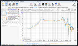
Alright, lets make this even more interesting.
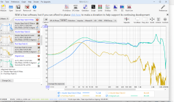
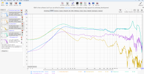
The purple line is the frequency response taken inbetween the port and the woofer. So basically this is the interfence that would be leaking into the measurements.
In a perfect world I could remove this response from each the port response and the woofer response to get my actual response for each of those, however, this world is not rainbows and unicorns so we do not know how much of the interference is from the port and how much is from the driver.
What we do know is that the respones ARE leaking into each other. At least this is getting somewhere.
I do not know of a way to entirely fix this. Does anyone? Does anyone have at least a suggestion of what to do? Just go with the woofer nearfield for crossover purpose and call it a day? Hope for the best?
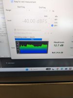
Also, watching the background noise of when REW is taking sweeps I am seeing quite a lot green. Do you think this is getting into the recorded response or does REW do a really good job of removing this? I am taking 8 measurement sums as people walk around in the unit above my shop.
The purple line is the frequency response taken inbetween the port and the woofer. So basically this is the interfence that would be leaking into the measurements.
In a perfect world I could remove this response from each the port response and the woofer response to get my actual response for each of those, however, this world is not rainbows and unicorns so we do not know how much of the interference is from the port and how much is from the driver.
What we do know is that the respones ARE leaking into each other. At least this is getting somewhere.
I do not know of a way to entirely fix this. Does anyone? Does anyone have at least a suggestion of what to do? Just go with the woofer nearfield for crossover purpose and call it a day? Hope for the best?
Also, watching the background noise of when REW is taking sweeps I am seeing quite a lot green. Do you think this is getting into the recorded response or does REW do a really good job of removing this? I am taking 8 measurement sums as people walk around in the unit above my shop.
Attachments
This is the impulse set wayyyyyy out at 300ms.That also winds up being the resolution of your measurement though. So, if you use a 50 millisecond long window, your lowest valid frequency and limit of resolution are both 20 Hz. That's not enough resolution to see some of this stuff. Try lengthening the window to 200 or 400 milliseconds and see if more detail shows up. Keep lengthening the window until no more low-frequency details develop.
No, I mean the woofer back wave at higher frequencies coming out of the port. You want the port output at port/box volume resonance, but nothing else coming out of the port (optimally). In practice, some of the midrange can bounce around inside the box and leak out through the port. Including more absorption between the woofer and port might help (if that's a problem - I'm still not sure your measurements are showing everything that's going on).
Attachments
How thick is you baffle and walls?frequency response taken inbetween the port and the woofer
And what amp/receiver do you use to make REW measureent?
Connected HDMI ?
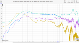
That's more like it.wayyyyyy out at 300ms
Another approach to the port wall thickness question would be to wrap the current one in the same damping sheet you applied to the outside of your midrange chamber and remeasure. If you have that lying around already, it would quickly let you know if it's an issue.
I think that's it.That also winds up being the resolution of your measurement though. So, if you use a 50 millisecond long window, your lowest valid frequency and limit of resolution are both 20 Hz. That's not enough resolution to see some of this stuff. Try lengthening the window to 200 or 400 milliseconds and see if more detail shows up. Keep lengthening the window until no more low-frequency details develop.
No, I mean the woofer back wave at higher frequencies coming out of the port. You want the port output at port/box volume resonance, but nothing else coming out of the port (optimally). In practice, some of the midrange can bounce around inside the box and leak out through the port. Including more absorption between the woofer and port might help (if that's a problem - I'm still not sure your measurements are showing everything that's going on).
Basically a mirror image of what I expected from the winisd sim.
Thank you everyone for all your help.
Attachments

I wish I could do that but I cannot. The hole in the enclosure is only big enough to fit the port in. Not big enough to fit the port with any material around it.That's more like it.
Another approach to the port wall thickness question would be to wrap the current one in the same damping sheet you applied to the outside of your midrange chamber and remeasure. If you have that lying around already, it would quickly let you know if it's an issue.
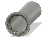
I do plan to reprint the port. This one is just for testing. The new one will be dimpled and made with a much smaller nozzle size for detail. Large nozzles print way faster but you lose detail.
Attachments

- Home
- Loudspeakers
- Multi-Way
- Need some help with my woofer and its port. Getting huge rise in deep bass out of this Peerless 8"