Mutuano said:GM,
Thank you for your inputs.
Unfortunately I don't know how to add 3 pictures per post...
I'll add 1 pic per post just for your appreciation.
Hope this helps.
Please remind that this is the rev#2. I'll post the revision #3 sooner.
Many thanks,
Greets!
You're welcome!
Do you draw for a living? I mean these look very nice, but they're way too time consuming for just a simple speaker design.
Anyway, the only way I know to post multiple pics is to upload them to Photobucket or similar hosting site and then use the special links to embed them in your post.
GM
Hi GM,
Nope! I just draw for fun. Actually it's taking 30min to make one of these.
Actually these drawings will be helpful for many reasons:
. for your visualization – I can be 100% sure that I’m doing it right;
. for cutting and assembling – I will send it for a 3rd part;
And it's part of my therapy 😀
Thanks for the tip about the photobucket.
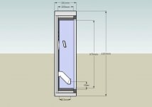
Here you can find revision 3 including modification suggested by you and Kevin.
Hope it’s OK. I’m anxious to get the final version and send it for cutting...
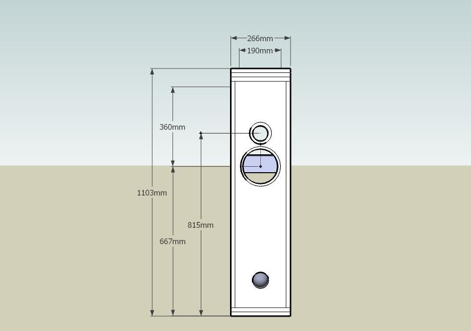
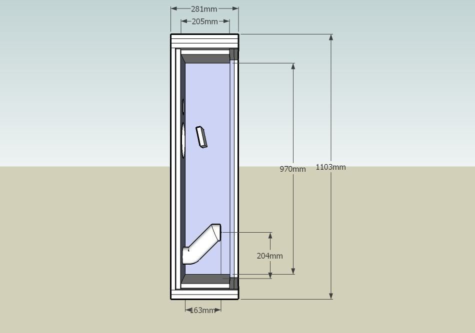
Thanks and regards to all,
Nope! I just draw for fun. Actually it's taking 30min to make one of these.
Actually these drawings will be helpful for many reasons:
. for your visualization – I can be 100% sure that I’m doing it right;
. for cutting and assembling – I will send it for a 3rd part;
And it's part of my therapy 😀
Thanks for the tip about the photobucket.
Here you can find revision 3 including modification suggested by you and Kevin.
Hope it’s OK. I’m anxious to get the final version and send it for cutting...
Thanks and regards to all,
Mutuano said:Hi GM, <SNIP>
...Here you can find revision 3 including modification suggested by you and Kevin.
Hope it’s OK. I’m anxious to get the final version and send it for cutting...
Hi Mutuano, looking good now. I especially like the removal of the brace. Regarding the port, I meant that the inner end should be at 102mm. I believe GM intended a straight port with one 45* elbow at the inside end. Since the port is so long I'm attaching an alternative solution which requires minimal changes on your part. My apologies if I have misunderstood the design, I'm going by the dimensions in your first post regarding port location.
Attachments
Hey GM and Kevin!
Are you both suggesting something like that?
GM firts
Kevin
Let's see if I'm getting this all info right...
Thank you!
Are you both suggesting something like that?
GM firts
Kevin
Let's see if I'm getting this all info right...
Thank you!
Kevin_Murray said:I especially like the removal of the brace.
I figure that the braces are more important than the double walls...
In an ML-TL it is usual to have the port at the end of the quarter-wave resonator.
dave
planet10 said:
I figure that the braces are more important than the double walls...
In an ML-TL it is usual to have the port at the end of the quarter-wave resonator.
dave
Hi Dave,
In most cases I'd agree with you, I've used them in my own design. In this case I think the cross section of the cabinet is small enough that with those walls it's unnecessary. Hopefully they never fall over 😉.
In any event I'm not designing the cabinet, I'm only trying to help it perform as designed. I like this project because it's not a copy of posted designs. Not that there's anything wrong with building someone else's design, I just like Mutuano's pioneering spirit.
Kevin
Kevin_Murray said:In most cases I'd agree with you, I've used them in my own design. In this case I think the cross section of the cabinet is small enough that with those walls it's unnecessary. Hopefully they never fall over 😉.
Big heavy unbraced walls lend themselves to energy storage... myself i'd leave the braces in and lose the extra layer of box.
dave
Mutuano said:Hey GM and Kevin!
Are you both suggesting something like that?
Greets!
You're welcome!
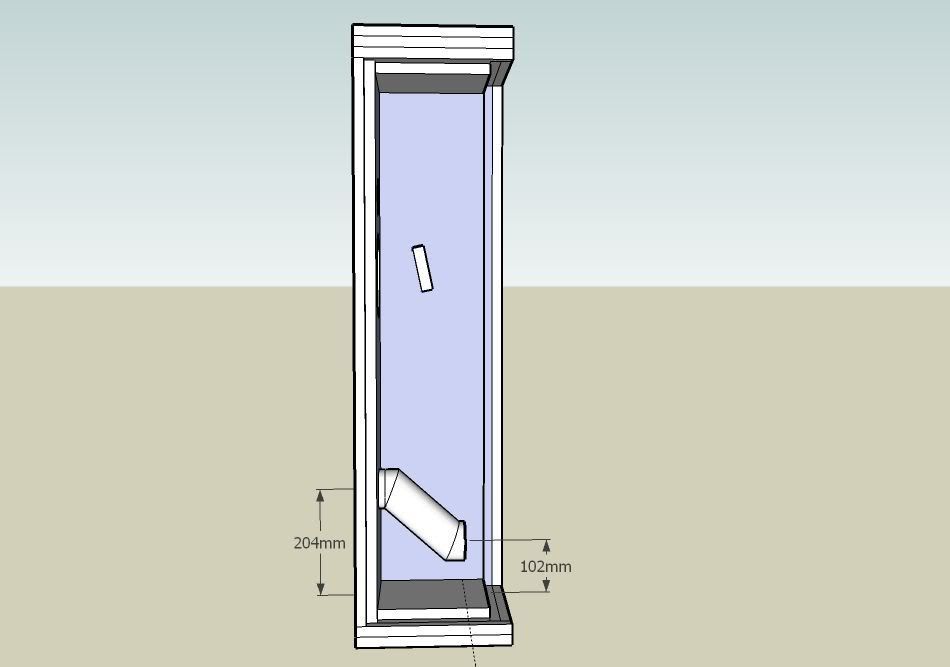
What I had in mind is a straight pipe with a 45 deg elbow (or 90 deg if more length is required) at the very inside end rotated to one side so that its entry distance from the driver doesn't change. Note that it will need a support either off the cab floor or rear wall to ensure it doesn't 'ring'.
WRT the diagonally cut pipe, this can work if its effective acoustic length tunes it to your satisfaction.
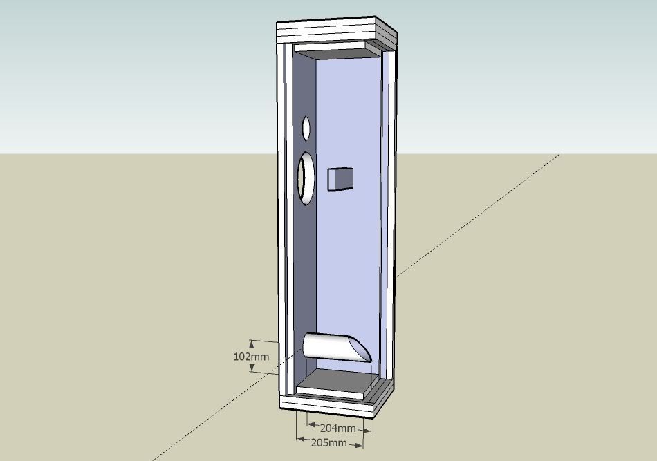
What's the deal with the slanted board behind the driver cutout? I mean if it's to brace/support/mass load the driver to the cab (which we want) it needs to be parallel to it.
GM
planet10 said:Big heavy unbraced walls lend themselves to energy storage...
This is true, but if they are stiff/massive enough though, then it's shifted to below the driver's passband and since the most efficient way to do is either by increasing material thickness and/or its density, doubling up 19 mm pushes it much further down in frequency than a single sheet/'Swiss cheese' braced construction at the expense of much increased weight. Factor in the tuning frequency and this driver's limited ability to pressurize it, then if I understand the theory correctly, with a ~equivalent stiffness of 1" BB or Appleply 11-13 ply plywood we've reached the point of diminishing returns of increasing thickness/damping, but have no measurements to prove it, so as always YMMV.
FWIW my 'test' is if you can stand a ~square edged coin on its top plate and play the lowest frequency music you listen to at whatever constitutes high SPL for the system without it 'dancing' around and/or toppling over, it's plenty good enough IMO.
GM
GM said:
Note that it will need a support either off the cab floor or rear wall to ensure it doesn't 'ring'.
Do you mean spikes?
GM said:
WRT the diagonally cut pipe, this can work if its effective acoustic length tunes it to your satisfaction.
I guess that will be easier for tunning. It's just push or pull the pipe in and out of the cabinet. Hope that works...
GM said:
What's the deal with the slanted board behind the driver cutout? I mean if it's to brace/support/mass load the driver to the cab (which we want) it needs to be parallel to it.
Like that?
Please let me know if I'm going right!
Many thanks for all help.
PS: Just for record: I'm in revision #4
Port length
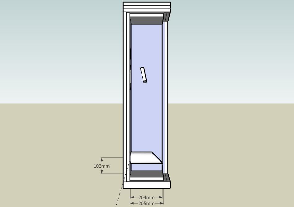
Mutuano, something is wrong here, there should be no need for an angle cut or elbow in the port. Forgive me if I missed a design change somewhere but the port should not even intrude as far as the middle of the cabinet. The design (GM's) calls for a 4"(~102mm) long port and a cabinet depth of 8"(~204mm). After factoring in the front baffle thickness the port should only end up 2.5"(~68mm) inside the cabinet.
GM did I miss something?
Kevin
Re: Port length
Greets!
Yes and no, apparently Mutuano is designing for a 'worst case' scenario I proposed, so wants to get the details right just in case a long vent is required:
http://www.diyaudio.com/forums/showthread.php?postid=1373859#post1373859
"I imagine you'll want to lower its tuning to around Fs with up to a ~204 mm long vent, which will require an elbow, so initially make the vent removable and use Play Doh or similar to temporarily seal it, ergo no need to flush mount it during tuning."
GM
Mutuano said:Like that?
i'd rotate it 90 degrees so that it is edge on. This will be stiffer and present less reflective surface so close to the driver.
dave
Re: Re: Port length
Ah thanks. I missed that.
GM said:Greets!
Yes and no, apparently Mutuano is designing for a 'worst case' scenario I proposed, so wants to get the details right just in case a long vent is required:
GM
Ah thanks. I missed that.
planet10 said:
i'd rotate it 90 degrees so that it is edge on. This will be stiffer and present less reflective surface so close to the driver.
dave
I like this idea. A semi-circle relief could be cut out of the front edge for the motor vent, without losing stiffness.
Kevin
Mutuano said:
I've been thinking to build a straight MLTL in a 6' midbass + 1' tweeter configuration with a midbass which has the following T/S parameters:
Fs = 36Hz
Qts = 0.34
Qms = 2.81
Qes = 0.38
Vas = 31 L
Re = 6.9 Ohms
Le = 0.34 mH
Sd = 0.0131 m2
BL = 7.6 T-M
Sens = 87.98 dB
Hi Mutuano
this spk I can help design for you!
planet10 said:
i'd rotate it 90 degrees so that it is edge on. This will be stiffer and present less reflective surface so close to the driver.
dave
If it is to be a solid board as shown, I'd agree with the caveat that I don't like putting such an obstacle in the pipe's loading dimension either, so either way it needs to be 'ventilated' with cutouts to reduce early driver reflections for the former or minimal pipe airflow restriction for the latter.
Anyway, I took it as merely a representation, not the finished product and wanted to make sure the basic cab details were finalized before getting into more driver mounting detail since apparently Mutuano has chosen not to use a variation of HJ's adjustable mass loading/bracing system.
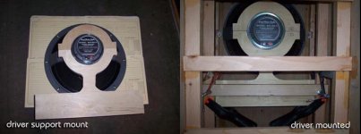
FWIW, here's Jay Fisher's realization of a 'conversation' I had with him, which uses an adjustable motor pinch bolt clamping brace that's lined with felt. For a wider BW driver such as the KB6, the broad base cross-member would be hollowed out and wrapped with either felt or acoustic fiberglass insulation:
GM
Attachments
Re: Re: Need some help for designing a MLTL
Greets!
Since he has already done a design that appears to be quite good to some of us, your offer to help implies you can measurably improve on it, so I am curious to see your design.
GM
jam-huang said:
Hi Mutuano
this spk I can help design for you!
Greets!
Since he has already done a design that appears to be quite good to some of us, your offer to help implies you can measurably improve on it, so I am curious to see your design.
GM
Mutuano said:
Do you mean spikes?
I guess that will be easier for tunning. It's just push or pull the pipe in and out of the cabinet. Hope that works...
Spikes?! To support/brace a vent tube?
Moving the vent in/out of the box doesn't change the tuning enough to matter, adjusting its length does, so you cut several different lengths from shortest to longest that you think you'll need and if none satisfy you, then try longer/shorter ones until you find one that does and if it winds up being < 1" to the back wall, then you'll need to curve it left or right to clear it and maintain the same acoustic length to the driver.
GM
Originally posted by GM
If it is to be a solid board as shown, I'd agree with the caveat that I don't like putting such an obstacle in the pipe's loading dimension either...
Good point, I was thinking the same earlier when I saw the long port. Has anyone ever done before & after tests with a driver brace? I'm wondering if it's worth the effort? I know B&W attempts to de-couple the driver from the cabinet entirely. If anyone know's if there is any info online could you post a link please?
I take back what I said earlier about a relief cut into the brace for the motor vent. It doesn't have one from what I saw in the photo.
Kevin
- Status
- Not open for further replies.
- Home
- Loudspeakers
- Multi-Way
- Need some help for designing a MLTL