Hi Greg,
I don't know what vintage or revision my bought-new-in-1983 unit is but I remember it originally had some really cheezy plastic knobs on it. I replaced those with the anodized aluminum ones PS changed to for the remainder of PS IV production.
For this reason I've always assumed I had an early version.
Maybe Doug can clarify. Or tell us if these revisions were made to improve SQ, or for reliability/production efficiency/parts availability reasons.
Mine was bought from a small dealer/speaker builder near Lansing Michigan (Unity Audio for those of you who really dig the obscure). He modified mine by removing all traces of AC in the unit:
No AC sockets on the back panel.
No AC wiring to the power switch.
Rectifier diodes cut from pc board.
Unique high-current power supply built from a Model 2 power amp & chassis, with a full bridge rectifier in the power supply so only DC was fed into the preamp.
I'm not sure what other mods were made. I just liked what I heard in his studio so asked him to build me one.
Later I added some better RCA jacks on the back and replaced the internal ribbon wire with litz wire.
OK, a little more information, but still no success.
I replaced the wrongly installed 7812 regulator, matching in, out and ground to their original positions as shown on the circuit by moving the reg over by one hole and pulling the third leg of the reg around the others over to position one. Having replaced this twice now, that part of the board is getting pretty beat, and I had to use a fine wire to replace the needle-thin trace from the output end of the reg. I did verifiy with a VOM that the legs are correctly tied into the circuit per the diagram.
This did not fix the problem. Now, the LED doesn't blink or come on at all and I don't hear the relay chirping, so the timer circuit is not working.
Checking voltages, transformer is still delivering the nominal 27.5 vac on both halves. On the leg nearest the rectifiers, R11 reads 37.5vdc (and it's still getting pretty hot); the same point on R13 reads about 25vdc. Post-regulation rail voltages are as before: positive rail can be adjusted to 33.5v, negative one won't go above 25v. Voltages off the rectifier bridge are 37.5 vdc to ground for the positive rail, and just 25v for the negative rail which explains why I can't adjust that rail upward.
In diode testing mode, D1–5 all read close to 5.2v in the correct polarity.
I'm guessing the next thing to try is to replace the two errant 1N4004 diodes, since they're where the trouble seems to start. I have a bunch of 1N4007s here--assuming those will be OK in this application. However, this really doesn't explain why R11 is overheating (145 °F), or why the timing circuit isn't working--or does it, since it appears to be connected to both rails.
Happy to have any suggestions.
Randy,
With all due respect, we are flying blind here. Replacing any more parts without knowledge of what's going on is unlikely to fix the problem and will just risk more damage to the old board traces. So please don't do that until we know more and can make informed suggestions.
Please provide the info I asked for in a previous post:
- 1st, confirm whether the power switch connects the negative rail to R11 (220R) resistor when turned on... or when turned off. Again, I am assuming when on, but can't tell for sure based on the schematic. Knowing this will help us understand how the relay timing circuit works.
- 2nd, trace the connections for the 78L12 in the relay timing circuit to confirm that the numbers on the schematic match pads for a pinout of 1-2-3 from left to right. I know you checked this before, but I am not sure you checked it how I intended... sorry for my lack of clarity. Confirm that the 78L12 pad at #1 connects to the junction of C7 & C8. Confirm that the 78L12 pad at #2 connects to R14 and both NE555P pins 8. AND confirm that the 78L12 pad at #3 connects to C9 R12 and C11_
- 3rd, confirm that the outputs are muted (shorted to ground) when the power is off. Again I assume that is true, that is how every mute circuit I am aware of works, but best to confirm.
If you need more info on any of those things, please let me know. Those things will help us better analyze what the circuit is actually doing.
Then...
- Lift one leg each of R11 and R13 to disconnect the relay timing circuit from both the positive and negative rails. See if you can adjust the negative regulator to the desired -33V.
- IF you can adjust the negative regulator to -33, then we can troublehoot the relay timing circuit . IF you cannot, then we need to go down a different path to troubleshoot at least the negative rail and regulator. That would start by disconnecting both regulator outputs from the distribution board so they are not supplying any downstream circuits with power. Then check to see if you can adjust the negative regulator output to -33V again. These will let us know appropriate next test steps. AND if the issue likely lies in the regulator circuits, I can use the regulator board I have here (that was working when I last checked... and will confirm) to ID what points to measure on your regulator board.
ALSO, SINCE you did not replace diodes D6-D13, DON'T at this point. We will need some voltage measurements to know more bout what is happening and we can provide suggestions on next steps then.
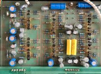
Another helpful thing to provide is a updated picture similar to that in post #55, but showing a closeup view of the regulator and relay timing board and another of the main active circuitry board.
Please do these and provide us the results in the thread. AND then we can confirm next steps.
Greg.
P.S. On using solder wick on the old board, it sounds like you may be using a fairly large size. The size I used on the old PS Audio boards I have here is Chem-Wik Size .050 (5-50L P/N). It is small and it takes a longer bit of wick, but because it is small you are not heating the board anymore than needed to liquify the solder.
With all due respect, we are flying blind here. Replacing any more parts without knowledge of what's going on is unlikely to fix the problem and will just risk more damage to the old board traces. So please don't do that until we know more and can make informed suggestions.
Please provide the info I asked for in a previous post:
- 1st, confirm whether the power switch connects the negative rail to R11 (220R) resistor when turned on... or when turned off. Again, I am assuming when on, but can't tell for sure based on the schematic. Knowing this will help us understand how the relay timing circuit works.
- 2nd, trace the connections for the 78L12 in the relay timing circuit to confirm that the numbers on the schematic match pads for a pinout of 1-2-3 from left to right. I know you checked this before, but I am not sure you checked it how I intended... sorry for my lack of clarity. Confirm that the 78L12 pad at #1 connects to the junction of C7 & C8. Confirm that the 78L12 pad at #2 connects to R14 and both NE555P pins 8. AND confirm that the 78L12 pad at #3 connects to C9 R12 and C11_
- 3rd, confirm that the outputs are muted (shorted to ground) when the power is off. Again I assume that is true, that is how every mute circuit I am aware of works, but best to confirm.
If you need more info on any of those things, please let me know. Those things will help us better analyze what the circuit is actually doing.
Then...
- Lift one leg each of R11 and R13 to disconnect the relay timing circuit from both the positive and negative rails. See if you can adjust the negative regulator to the desired -33V.
- IF you can adjust the negative regulator to -33, then we can troublehoot the relay timing circuit . IF you cannot, then we need to go down a different path to troubleshoot at least the negative rail and regulator. That would start by disconnecting both regulator outputs from the distribution board so they are not supplying any downstream circuits with power. Then check to see if you can adjust the negative regulator output to -33V again. These will let us know appropriate next test steps. AND if the issue likely lies in the regulator circuits, I can use the regulator board I have here (that was working when I last checked... and will confirm) to ID what points to measure on your regulator board.
ALSO, SINCE you did not replace diodes D6-D13, DON'T at this point. We will need some voltage measurements to know more bout what is happening and we can provide suggestions on next steps then.
Another helpful thing to provide is a updated picture similar to that in post #55, but showing a closeup view of the regulator and relay timing board and another of the main active circuitry board.
Please do these and provide us the results in the thread. AND then we can confirm next steps.
Greg.
P.S. On using solder wick on the old board, it sounds like you may be using a fairly large size. The size I used on the old PS Audio boards I have here is Chem-Wik Size .050 (5-50L P/N). It is small and it takes a longer bit of wick, but because it is small you are not heating the board anymore than needed to liquify the solder.
Randy,
More thoughts... what we are trying to do is narrow down what are causing the problems:
- First, the unit developing a significant hum, which started your quest
Then after replacing some parts
- the negative regulator output limited to 27V max instead of the specified 32V-33V
- relay timing circuit stuck and not unmuting the outputs
Correct?
Going through your posts, here's what I see that you've done:
- replaced all electrolytics
- Adapted a replacement power switch
- Replaced the 78L12 in the relay timing circuit with what may not be a direct pin-for-pin replacement.
- Replaced the MPS8099, MPS8599, MJE172, & MJE182 transistors in the positive and negative regulator circuits
Did you change or replace anything else?
Then to actually resolve the issues, we need to narrow down what is causing each. The steps I outlined help us do that, by first letting us confirm whether the regulator circuits are working ok, fixing them if needed, then tackling the relay timing board circuit and fixing it.
Awaiting more info from you!
Greg in Mississippi
P.S. Other things worth getting flat...
Before you started replacing parts, did you happen to measure the positive and negative regulator outputs to confirm they were both at 32V-33V? Nottaprob if you didn't, the circuit should get there as designed and implemented.
The circuit shown in post #59 is of the PS Audio Model Two-C Plus Power Amp. While the regulator circuit is similar, it runs at different voltages. The circuits in posts #60 and #63 are the ones that most closely match what you have. I know it confused things at first, but I think all have gotten past that now.
Back in post #56 you referred to the MJE172 and MJE182 as regulators, but they are just transistors. In this unit the regulators are the full circuit, the MPS8099 & MPS8599 are transistors that with their surrounding components drive the MJE172 & MJE182 as pass transistors in the respective positive and negative regulator circuits. This is called a discrete regulator, distinct from the 78L12 which is a monolithic regulator that has a small circuit built into it.
I just took a few minutes and fired up the unit I have here with the regulator circuit board I posted a picture of in post #76. With +-37.5VDC input it outputs +-33VDC with no issues and both rails get up to roughly 36V easily. So it will be a good reference unit to use to troubleshoot yours.
@guy48065 describes the relay timing circuit well in post #64.
Also, @guy48065, I believe your unit was an early version. PS Audio went through a number of changes over the PS-IV run. I vaguely remember them using LM317 and LM337 regulator chips (which it appears yours has) initially on later versions of the PS-III (early versions like the one I initially purchased had no regulation) and going to the discrete regulator circuit part-way through the PS-IV run for SQ reasons.
I like the mods Unity Audio and you later did on your unit, all should have been worthwhile upgrades.
@Buckapound:
Greg has things exactly right here, including the historical info, please listen to him.
If the only original problem was some hum, and your efforts to correct this resulted in the negative power supply and mute circuit problems, then quite obviously some type of mistake was made causing these issues. Check for electrolytic capacitors installed backwards, solder bridges, semiconductors installed incorrectly, broken traces, etc. And follow Greg's step by step troubleshooting advice, to determine the fault(s) in a logical manner, instead of just randomly swapping out parts.
Take care,
Doug

Thanks, Greg and Doug, here's some info and photos. Really appreciate your help.
On Apr 28, 2025, at 7:54 AM, Randall Mosher wrote:
Power switch when in the "on" position connects the inboard side of R11 to pin 1 of the timer ICs. This means the schematic shows the switch in the "on" position.
Relay has four pins on either side (L+R), which appear to be, from front of unit to back:
1: chassis ground
2: fifth pin from right on connections from PS board to long board across front of unit, same as + connection to LED (output of timer circuit?)
3: preamp output, presumably connected to signal from preamp board
4: connected to output jack
As for the solder wick, I'm using MG Superwick #425 fine braid and a flux pen.
On Apr 28, 2025, at 7:54 AM, Randall Mosher wrote:
- 1st, confirm whether the power switch connects the negative rail to R11 (220R) resistor when turned on... or when turned off. Again, I am assuming when on, but can't tell for sure based on the schematic. Knowing this will help us understand how the relay timing circuit works.
Power switch when in the "on" position connects the inboard side of R11 to pin 1 of the timer ICs. This means the schematic shows the switch in the "on" position.
Connects to ground for sure, so yes, since C7 & C8 are right there.Confirm that the 78L12 pad at #1 connects to the junction of C7 & C8.
Confirm that the 78L12 pad at #2 connects to R14 and both NE555P pins 8.
Yes to both. My assumption is that pin 3 is the input since it's closest to the + power. Correct, or do I have 2 and 3 backwards?AND confirm that the 78L12 pad at #3 connects to C9 R12 and C11_
Mute does not appear to short outputs to ground. No continuity from signal output jacks to either star ground or ground of RCA jack when power off. Appears to just disconnect signals from output jacks.- 3rd, confirm that the outputs are muted (shorted to ground) when the power is off. Again I assume that is true, that is how every mute circuit I am aware of works, but best to confirm.
Relay has four pins on either side (L+R), which appear to be, from front of unit to back:
1: chassis ground
2: fifth pin from right on connections from PS board to long board across front of unit, same as + connection to LED (output of timer circuit?)
3: preamp output, presumably connected to signal from preamp board
4: connected to output jack
As for the solder wick, I'm using MG Superwick #425 fine braid and a flux pen.
Attachments
Randy,
Thanks for the information. This helps understand what's going on in the circuit.
The next thing is to resolve the negative regulator issue. Why? We don't know if it is caused by:
- replacing caps or transistors in the regulator circuit
- replacing caps in the main circuit
- replacing caps or the 78L12 in the relay timing circuit
- or something else.
The only way to effectively troubleshoot it is to isolate the regulator circuit from the main and relay timing circuits. AND if both the positive and negative regulators work ok in that configuration, you can selectively reconnect the main and relay timing circuits separately to ID or eliminate each as the cause of the negative regulator issue.
One way to do this with less damage to the delicate component pads is to find an area in connecting traces at least 1/2" away from any pads where you can cut the trace with an X-Acto, other hobby, or sharp utility knife. It only takes a single cut in most cases to sever the connection, though it usually takes some cutting into the substrate to ensure the trace is fully cut. Of course check for continuity across the cut to confirm. Then you can reconnect it with a solder bridge... or solder cut-off component leads across the cut. Though not usually done when professionally repairing a unit, I have found this very helpful in working on my own gear.
Use this method or any other to isolate the regulators from the main and relay timing circuits. Then report back on whether both the negative and positive can be adjusted to spec.
On identifying the proper way to install the replacement 78L12 regulator, we really need the voltages at the regulator pads AFTER the regulators are both working to spec AND without the regulator chip in circuit. Since they are almost a dime a dozen, I suggest cutting the leads of the 78L12 you have installed as close as you can to the body of the regulator (and discarding it). Then you can measure there without disturbing the board pads and traces. If it helps, you can solder short pieces (3"-6") of insulated wire to the remaining lead ends and measure from the other ends of those. AND in trying a replacement regulator once the main regulator circuits are workin to spec AND we understand more about the relay timing circuit, you can solder a replacement 78L12 to the end of those leads (as long as they are no longer than roughly 6") and we can try different orientations (if needed) without further endangering the traces and pads.
BUT 1st let us know how the regulator circuits behave when isolated from the main and relay timing circuits.
Thanks!
Greg in Mississippi
Thanks, Greg, appreciated.
Having (again) compared the photos I took before the re-cap against the actual unit, I can confirm that all the electrolytic capacitors are in their correct orientations. The transistors in the main regulation circuit are number-for-number replacements installed in their correct orientations.
I will first detach the timer circuit and see what difference that makes, using the trace-cut method you described (and I was thinking of as well). If the main reg then outputs the correct voltage on the negative rail, then the problem is likely to be the timer circuit. It does seem odd to me that it's the negative side of main the power supply that I can't get up to proper voltage, yet this the one connected to the timer circuit via a high resistance value (6.8k) from the diode bridge on the PS board, so is unlikely to be drawing excess current. It's the positive 220r resistor on the + side that's excessively warm.
If I need to remove/replace the 7812, I have some tiny silver-plated forked terminal posts I can solder in from below, so I can replace the reg chip from above with no further damage to the board.
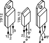
I would love to know if I have that regular chip installed in the correct manner. Based on the schematic, can you or anyone identify the in and out leads and if I have them labeled correctly in both the 78L12 and 7812 drawings (as installed) attached to my last post. This would have been easier If I could have found a datashgeet for the old version in that oddball chip package and pinout. I can't even figure out the case type number.
Will report back when I have a chance to cut some traces and measure.
--Randy
Having (again) compared the photos I took before the re-cap against the actual unit, I can confirm that all the electrolytic capacitors are in their correct orientations. The transistors in the main regulation circuit are number-for-number replacements installed in their correct orientations.
I will first detach the timer circuit and see what difference that makes, using the trace-cut method you described (and I was thinking of as well). If the main reg then outputs the correct voltage on the negative rail, then the problem is likely to be the timer circuit. It does seem odd to me that it's the negative side of main the power supply that I can't get up to proper voltage, yet this the one connected to the timer circuit via a high resistance value (6.8k) from the diode bridge on the PS board, so is unlikely to be drawing excess current. It's the positive 220r resistor on the + side that's excessively warm.
If I need to remove/replace the 7812, I have some tiny silver-plated forked terminal posts I can solder in from below, so I can replace the reg chip from above with no further damage to the board.
I would love to know if I have that regular chip installed in the correct manner. Based on the schematic, can you or anyone identify the in and out leads and if I have them labeled correctly in both the 78L12 and 7812 drawings (as installed) attached to my last post. This would have been easier If I could have found a datashgeet for the old version in that oddball chip package and pinout. I can't even figure out the case type number.
Will report back when I have a chance to cut some traces and measure.
--Randy
Randy,
Several things...
1st, seeing the caps you put in, you may or may not be aware that the unit will almost surely sound different with those parts. The "Panasonic Purple" caps as PS Audio called them were specifically selected for their sonic signature. I am not familiar with any of the brands and lines of caps I saw that you used, but my experience is that they won't sound the same as new "Panasonic Purple" caps, much less 40 year+ old ones.
& in my experience, you need to run the unit a couple weeks before the sonic signature of the new parts settles in. SO once you have it running, don't make hasty decisions.
IF the sonic signature once this is all sorted doesn't match your tastes, I can suggest Nichicon UKZ, UFG, UKG, and UFA lines along with United Chemi-Con KYB line as ones I have used and found to sound good to my ears and in my setups. I personally have not liked any recent Panasonic nor the Elna SilMilc lines that I have tried. BUT YMMV.
2nd, I have spent WAY TOO MUCH TIME explaining reasoned paths forward to resolving your issues AND THEN responding to you not following those paths.
THAT STOPS NOW.
I will only engage again when:
1st, you have confirmed whether the regulator circuits work as expected with BOTH the main circuitry and relay timing circuit not connected. IF they don't, we can resolve the regulator circuit issues. ONCE OR IF they do, we can go onto the next issue, that of the relay timing circuit.
2nd, ONCE the regulator circuits are working as expected & that you have reconnected them TO ONLY the relay timing circuit AND removed the replacement 78L12 from the circuit AND measured the voltages at the 3 pins. With that information we can then speculate on next steps with the relay timing board and get it working or replaced.
AND ONLY THEN confirm the full preamp works and deal with any unknown as yet issues.
These are critical steps in understanding what is happening. & IMHO doing anything else just delays finding out what is needed to resolve the issues.
I won't spend anymore time going down other paths.
For that, you are on your own.
Greg in Mississippi
P.S. Of course there is still the path of picking up one of the PS-IVs on EBay once you have confirmed it has at least a discrete regulator / relay timing board similar to yours and a similar-revision-level main circuit. AND either using it as a control for troubleshooting OR transferring boards/parts over OR just using it. The one that was list at $100 with no power supply is now at $85 Buy It Now and a $60 bid price. The one that was complete and listed at $600 is now at $360. AND another is listed with no power supply at $139 with offers possible. & others.
Sorry to offend, Greg. It was not my intention to disrespect your time or expertise.
As I mentioned in my last post, I'll cut some traces and see what happens.
--Randy
As I mentioned in my last post, I'll cut some traces and see what happens.
--Randy
Sorry for the long delay. Life intrudes rudely as you all know. Anyway, here's an update:
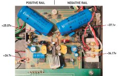
As Greg suggested, I cut the connections before R11 and R12, leaving the delay/blinking circuit isolated. I also cut connections from the regulator circuit to the pins at the front of the regulator board that power the preamp sections. To make things easier on this fragile board, I installed tiny forked terminal pins on either side of the cuts. As their bottom pins are hollow, I used a spring-loaded center punch to flare the ends and make a secure mechanical connection to the board. I then soldered them onto the traces and verified they were electrically connected to the traces and also separated from their loads.
DC voltages at both points are shown on the photo. AC voltages remain at 27.7v for each half of the transformer. Turning the trimmer on the negative rail got the output voltage up to 35v, but at that point the trimmer was smoking a little. Not sure what to make of that.
Thoughts on how to proceed? It does appear that the trouble is very early in the circuit, and this problem was showing before I disconnected the loads. Just FYI, the bridge and other diodes near the back of the board close to the AC input have not been replaced.
--Randy
Attachments
That's interesting.
In that circuit, there should be VERY little current flowing across the trimmer resistor.
Also as I said in post #s 69, 71, 76, & 83, the traces that have to be cut to disconnect the regulators from the relay circuit are before resistors R11 (220R 1/2W) & R13 (42.4K? 1%), not R12. IF you did disconnect at R12 instead of R13, reconnect there, but now disconnect before R13 & recheck.
Some things to check after you get it disconnected at R13:
- With the power off and the electrolytic caps fully discharged, check as many points as you can in the regulator circuit to see if anything is shorted to ground that should not be. According to the schematic, there should only be 10 connections... 2 for the main filter caps C & C2, R1 & R2, D11 & D12, the trimmers R8 & R9, and the output filter caps C4 & C5. There may also be additional smaller value bypass caps across the main filter & output filter caps.
- With the power on, measure the voltage across the + & - of each of the 2200uF main filter caps & let us know what you find. Should be about 37V across each.
Also:
- Remind us, what all did you change/replace in the regulator circuits?
- & you should find some replacement 5K trimmers as one that was smoking will not likely be accurate and reliable anymore.
Greg in Mississippi
P.S. Was not trying to be preachy about my mentioning of R13 disconnection, sorry if it came off that way. I was concerned I had given you the wrong disconnect point, searched and AFAIK I did not and those were the posts I found.
Greg in Mississippi
Greg in Mississippi
- Home
- Source & Line
- Analog Line Level
- Need PS Audio PS IV schematic