Greg Stewart,
Im new to this board and it seems your a a google account of Vintage Audio?!
I could as well use the Service Manual for the PS IV Preamp please as I wish to cap mine
and having a list makes it so much easier 🙂 I’m not a pro but been repairing Vintage audio for 30 years,
mostly Carver as there seems to be a lack of Service manual for PS Audio such as my Power amp one with Linear and pre amp, recently recapture and upgraded my Carver TFMx Amp what a …… to take this think apart,
Sunfire don.t touch only Bill in WA has the service manual not to mention all caps are Chinese, though
just because I Love my friend I recapt his Sunfire Ultamate Receiver 160 caps only I be so stupid LOL
Mother Board, Power board and main amp board.
Anyhow looking forward to intermingle here and who knows maybe to help others as you do.
Hope you get to read this.
Thank you kindly in advance.
LOL, not associated with "Vintage Audio" though I have & have had a lot of vintage audio.
I guess it goes with being a vintage DIY audio buff!
PM me your email, I'll get you all the PS Audio info I have.
Greg in Mississippi
I guess it goes with being a vintage DIY audio buff!
PM me your email, I'll get you all the PS Audio info I have.
Greg in Mississippi
Greg,
Please forgive me I meant diyaudio lol
Ones I get approved to be able to PM here I will do so.
On another note, would you by any chance have anything in the Infinity Rs0.2 speakers?
Thank you kindly Jens
Please forgive me I meant diyaudio lol
Ones I get approved to be able to PM here I will do so.
On another note, would you by any chance have anything in the Infinity Rs0.2 speakers?
Thank you kindly Jens
I still have the preamp, actually I have 2 of them. The hand drawn schematic not the service manual I had (that I got from Greg) almost a decade ago, was on my pc that developed a major case of bohemian hemorrhoids died few years ago. I lost everything on the pc.
Have not used the pre amps in many years!.
Regards,
Art
Have not used the pre amps in many years!.
Regards,
Art
Art, sweet, got an extra push button?
when I took them apart to detox the switches and one spring just said good buy.
PS audio send me an Owners manual it has a little schematic not match though.
when I took them apart to detox the switches and one spring just said good buy.
PS audio send me an Owners manual it has a little schematic not match though.
Jens,
Nottaprob on the mis-association.
See if what I sent to you via PM works ok.
I may have some of those pushbuttons if they are what I remember, post a picture.
& sorry, I don't have anything on those speakers
Greg in Mississippi
Nottaprob on the mis-association.
See if what I sent to you via PM works ok.
I may have some of those pushbuttons if they are what I remember, post a picture.
& sorry, I don't have anything on those speakers
Greg in Mississippi
Crappy picture I will take some tomorrow,
Inside they have a u shape bend plates with springs behind them, by the design I wonder if my various contact issue is even Oxy related.
That be awesome, are there any good upgrades beside maybe adding 2-Wima for the filter caps?
Inside they have a u shape bend plates with springs behind them, by the design I wonder if my various contact issue is even Oxy related.
That be awesome, are there any good upgrades beside maybe adding 2-Wima for the filter caps?
Attachments
Greg,
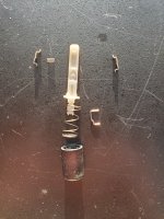
Here you go, the more I review this design the more I wonder if the issue with these switches is rather bad springs than Ox.
See if this helps to identify
These are a pain to put together, you can see on the one picture where the spring on the right is missing.
One picture assembl.
Here you go, the more I review this design the more I wonder if the issue with these switches is rather bad springs than Ox.
See if this helps to identify
These are a pain to put together, you can see on the one picture where the spring on the right is missing.
One picture assembl.
Attachments
I'll look & see if I have one here... It might be a few days or more, sorry!
Greg in Mississippi
Greg in Mississippi
Sorry. I'm ok, but an unexpected water heater replacement, moving all the stuff I had in the way out, & slowly reorganizing (&/or trashing) has kept me busy. No estimates on when yet, keep on me!
Greg in Mississippi
Greg in Mississippi
Thx. Caught it just in time before serious leaking. Had to clear out utility room into already overcrowded garage to have it replaced, slowly getting things re-organized / re-stored and/or trashed if no longer needed.
Will keep watch for those parts.
Greg in Mississippi
Will keep watch for those parts.
Greg in Mississippi
Another PSIVH Rebuild?
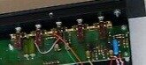
Hi all, I've been using one of these for years. When I bought it on eBay, the phono section had some hum, so I've been using another phono preamp. The pre otherwise has been working fine apart from a scratchy volume pot, but this week suddenly developed a significant hum.
I was thinking I would just gut the thing and install a different preamp board, perhaps Wayne's BA line amp. But then I opened it up and realized that it would be quite a lot of work if I wanted to maintain the same function for all the knobs and switches. I don't have any sentimental attachment to it, but it is a very well constructed piece of kit, and honestly it might be just as easy to fix it as gut it, and that would also preserve its value.
So, the question is, what parts should I replace that are most likely to fix the hum problem on both phono and line pre? I assume all the electrolytics would be prime targets. Anyone think this alone will fix the issues? Anything else likely contributing to the problem? As you can tell from the photo, it's in pristine condition, and the ground connections are tight. Once I get the board out, I'll check for cold solder joints. Also, I haven't found a rebuild kit anywhere--is there one or even a BOM?
Looks like the best way to get to the bottom of the board is to unbolt all connections and controls and just lift everything out. Not too bad, just a bunch of nut driver work.
Thoughts on how to proceed?
OK, I've replaced all the electrolytics. Circuit boards get pretty scary after 40 years, but I only had a couple of lifted/torn pads, which I was able to fix.
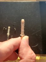
Someone mentioned the switches a few posts back. I noticed the power switch wasn't working, and when I looked at it, the nylon thing in the center had cracked in half right at the zigzag channel where the wire travels. Uh-oh. Miracle of miracles, I had an almost exactly compatible Alps switch in my parts bin that fit perfectly after I widened and deepened the metal channel that holds the switches in place.
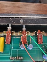
It's all back together and there seems to be a voltage issue, so I'm looking for suggestions. This unit seems to have a separate power supply that monitors the B voltage and flashes the LED if insufficient. The unit turns on as normal, LED flashes for a few seconds and stabilizes, then it starts flashing again, indicating low/no voltage.
I should say that I replaced the original 78L12 regulator in the power supply for the LED flasher circuit, as it clearly had been overheating, with a little heat damage to the board. I used a 7812C chip in a TO-220 case and stuck a small heat sink on it, thinking that would be a drop-in replacement. There seems to be a whole power supply circuit for this LED flasher thing, fed from the transformer according to the circuit diagram.
There are six pins on the PS board that connect it to the wide distribution board that connects to everything else in the unit. Let's just call them pins 1–6, from left to right, reading from the front of the unit. I get different voltages when the LED is stable than when it is flashing. Between pins 1 and 2, I get 45.3 and 37.7 respectively, with pin 1 being positive. Between pins 5 and 6, it's lower: 28.7 and 24.9, with pin 6 being negative. The MJE172 regulator on the right side is running a few degrees warmer than the MJE182, just a few degrees above ambient. Transformer is showing ~26.7VAC on both halves, so I don't think there's a problem with that.
I've tried turning the trimmer resistor on the right side in the main power supply circuit counterclockwise, but I cannot get the voltage up over 29v.
Anybody care to diagnose? The only thing I can think of is replace the MJ172 regulator. Appreciate any help!
Someone mentioned the switches a few posts back. I noticed the power switch wasn't working, and when I looked at it, the nylon thing in the center had cracked in half right at the zigzag channel where the wire travels. Uh-oh. Miracle of miracles, I had an almost exactly compatible Alps switch in my parts bin that fit perfectly after I widened and deepened the metal channel that holds the switches in place.
It's all back together and there seems to be a voltage issue, so I'm looking for suggestions. This unit seems to have a separate power supply that monitors the B voltage and flashes the LED if insufficient. The unit turns on as normal, LED flashes for a few seconds and stabilizes, then it starts flashing again, indicating low/no voltage.
I should say that I replaced the original 78L12 regulator in the power supply for the LED flasher circuit, as it clearly had been overheating, with a little heat damage to the board. I used a 7812C chip in a TO-220 case and stuck a small heat sink on it, thinking that would be a drop-in replacement. There seems to be a whole power supply circuit for this LED flasher thing, fed from the transformer according to the circuit diagram.
There are six pins on the PS board that connect it to the wide distribution board that connects to everything else in the unit. Let's just call them pins 1–6, from left to right, reading from the front of the unit. I get different voltages when the LED is stable than when it is flashing. Between pins 1 and 2, I get 45.3 and 37.7 respectively, with pin 1 being positive. Between pins 5 and 6, it's lower: 28.7 and 24.9, with pin 6 being negative. The MJE172 regulator on the right side is running a few degrees warmer than the MJE182, just a few degrees above ambient. Transformer is showing ~26.7VAC on both halves, so I don't think there's a problem with that.
I've tried turning the trimmer resistor on the right side in the main power supply circuit counterclockwise, but I cannot get the voltage up over 29v.
Anybody care to diagnose? The only thing I can think of is replace the MJ172 regulator. Appreciate any help!
Last edited:
I know this is probably the least sexy project on this whole DIY forum, but I'm on the verge of chucking this preamp in the trash as I cannot figure out what might be wrong. I keep looking at the "What I fixed today" thread and thinking it would be nice to get this into that category.
As I mentioned, as part of a re-cap I replaced the voltage regulator that feeds the flashing circuit for the LED with what I thought was the same type but in a bigger case, as there was some evidence of overheating. This circuit is a bit mysterious to me and am not sure whether I should replace the regulator chip with another 78L12 like the one I pulled. Not sure if the overheating is just endemic to this product. It does seem to have happened over a long period of time—more bleached than scorched.
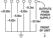
After tightening up a loose ground connection, the current status is this: the LED alternates between solid status and flashing every few seconds. I'm including a little diagram of the voltages to ground from the six pins adjacent to the PS board on the narrow strip that runs along the front of the case. As you can see + and – are both at a little over 33v—a bit short of the 38vdc the circuit diagram says they should be. I can adjust the trimmers lower, but I can't get the voltage much above 34v.
The four pins between the right- and left-hand ones all measure around 5v, which is a little confusing to me.
Any advice or thoughts would be most welcome.
As I mentioned, as part of a re-cap I replaced the voltage regulator that feeds the flashing circuit for the LED with what I thought was the same type but in a bigger case, as there was some evidence of overheating. This circuit is a bit mysterious to me and am not sure whether I should replace the regulator chip with another 78L12 like the one I pulled. Not sure if the overheating is just endemic to this product. It does seem to have happened over a long period of time—more bleached than scorched.
After tightening up a loose ground connection, the current status is this: the LED alternates between solid status and flashing every few seconds. I'm including a little diagram of the voltages to ground from the six pins adjacent to the PS board on the narrow strip that runs along the front of the case. As you can see + and – are both at a little over 33v—a bit short of the 38vdc the circuit diagram says they should be. I can adjust the trimmers lower, but I can't get the voltage much above 34v.
The four pins between the right- and left-hand ones all measure around 5v, which is a little confusing to me.
Any advice or thoughts would be most welcome.
Attachments
- Home
- Source & Line
- Analog Line Level
- Need PS Audio PS IV schematic