Nice and "tubey"! I quite like the sound with single-coil pickups, though I can hear some of the excessive midrange / bass you mentioned. That is very much a matter of personal taste, though....2 short videos...
I put the essentials of your treble tone control circuit into LTSpice, and simulated the frequency responses that would result....the values of the capacitors around the tone pots are not ideal for guitar signal.
<snip>
The bass is overwhelming everything unless I cut it out almost entirely.
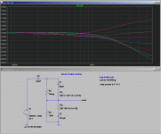
First, the stock circuit. As you said, treble adjustments start above 1 kHz, which is suitable for Hi-Fi, but not for guitar:
-Gnobuddy
I'll say up front that tweaking guitar tone controls is something I've personally found quite frustrating, and sometimes fruitless. So I'm not sure the changes I'm about to suggest will make you happy. But perhaps they'll at least suggest a starting point, so here goes!
Since you already have 2 Meg pots, and they are in working condition, I think you might as well keep them unless you find it impossible to get the results you want. New pots may produce new problems (changes in control feel, knobs not fitting, et cetera.)
So, what can we do with the stock 2 meg treble pot? Firstly, your treble Baxandall circuit will still work the same way if you increase or decrease both caps (50 pF and .001 uF) by the same ratio. In this case, we want bigger caps, so the tone control starts to work at frequencies lower than 1 kHz, where e-guitar still has enough output to be worth tweaking.
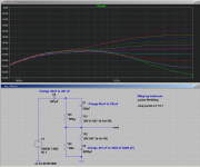
My suggestion is to increase the 50pF cap to 120 pF (i.e. multiply its value by 2.4 times). At the same time, increase the 0.001uF to 0.0022 uF (multiply it by 2.2, the nearest standard value).
By the way, 0.0022uF is the same as 2200pF, or 2.2nF. (For some inexplicable reason, we never use the SI "nano" prefix for caps in North America, so we use the clumsier and technically improper 0.0022uF or 2200pF terminology instead.)
This will move the effective range of the treble control down by a bit more than an octave, so it starts to have an effect above roughly 400 Hz, rather than only above 1 kHz.
You can of course try the same trick with other values, remembering to try and scale the original 50 pF and 1000 pF (0.001uF) caps by roughly the same factor each time. For example, you could try 180 pF and 3300 pF, or 220 pF and 4700pF, which will move the treble controls effective range even further down towards low frequencies.
Now let's consider the other problem - the overpowering bass. This is a common issue with guitar amps derived from Hi-Fi circuits. Leo Fender made the same mistakes with his 5E3 when he lifted Hi-Fi cap values from the back of the GE tube catalog, for instance.
Since you're working on the treble tone control circuit already, let's see if we can cut some bass there. The 0.02uF cap that couples the signal into the treble control pot (from the anode of the 6FQ7) is the obvious place to cut some bass. Based on your report of overpowering bass, I suggest replacing this with a 0.001uF (same as 1 nF, or 1000 pF). This drastic reduction (twenty times smaller!) will gradually roll off deep bass below 150 Hz or so.
As before, you can, of course, tinker with this to taste. You can reduce it even more if you still have too much bass, or increase it from 1000 pF if you now have too little bass.
The attached image shows what LTSpice predicts using the starting values I suggested in this post: 120 pF and 2200 pF on the tone control pot, and a 1000 pF coupling cap.
If you try out these changes, let us know how they sound!
-Gnobuddy
Incidentally, most of the valve guitar amps we hear use some variation on the tone control "stack" Leo Fender used in some of his classic amps. That circuit produces a sizeable mid frequency scoop at typical tone control settings.
You may find your Baxandall circuit sounds too midrange-dominant no matter what you do with the treble caps - if so, what you might need is a mid-scoop. If that time comes, we can discuss some of the options you have. The fact that you have so many valves on your donor chassis really gives you a lot of possibilities. 🙂
-Gnobuddy
Attachments
Gnobuddy,
Thank you again for the feedback, all your help has been an invaluable resource in this guitar amp conversion!!
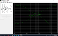
I appreciate you running a mockup of the treble circuit in LTSpice. I downloaded that program a while ago but have not been able to dedicate the time necessary to understanding and utilizing it properly. I have become familiar with Duncan Amp's Tone Stack Calculator, which I think is a simplified version of LTSpice focusing on just tone stack circuits. Using their standard James TS mockup and changing the values to reflect my circuit with your suggested changes to the treble I came up with the attached results. I think this is at least somewhat accurate to what I can expect then?
I think this may be the case. I understand that by boosting bass and treble at the same time in a James TS you can essentially make a mid scoop, but I don't think it is going to be nearly as much of a mid scoop as I'd like to get. What suggestions do you have if any for accomplishing this? If possible I'd like to keep the bass & treble as the only tone controls as those pots exist already. Could I redo the tone circuit with bass and treble adjustments but a fixed value set for mid range like an old Fender Deluxe Reverb TS? If so that may be the way I'd like to go...
Thank you again for the feedback, all your help has been an invaluable resource in this guitar amp conversion!!
I appreciate you running a mockup of the treble circuit in LTSpice. I downloaded that program a while ago but have not been able to dedicate the time necessary to understanding and utilizing it properly. I have become familiar with Duncan Amp's Tone Stack Calculator, which I think is a simplified version of LTSpice focusing on just tone stack circuits. Using their standard James TS mockup and changing the values to reflect my circuit with your suggested changes to the treble I came up with the attached results. I think this is at least somewhat accurate to what I can expect then?
You may find your Baxandall circuit sounds too midrange-dominant no matter what you do with the treble caps - if so, what you might need is a mid-scoop. If that time comes, we can discuss some of the options you have. The fact that you have so many valves on your donor chassis really gives you a lot of possibilities.
I think this may be the case. I understand that by boosting bass and treble at the same time in a James TS you can essentially make a mid scoop, but I don't think it is going to be nearly as much of a mid scoop as I'd like to get. What suggestions do you have if any for accomplishing this? If possible I'd like to keep the bass & treble as the only tone controls as those pots exist already. Could I redo the tone circuit with bass and treble adjustments but a fixed value set for mid range like an old Fender Deluxe Reverb TS? If so that may be the way I'd like to go...
Attachments
Put it this way, Tone Stack Calculator is a fantastic tool compared to what engineers had in the tube era. So much better than writing down equations and running numbers through a slide-rule!...LTSpice...Tone Stack Calculator...
That said, LTSpice is on another level altogether. It has a history going back to the early 1970s, when SPICE was created by genius researchers and grad students at Berkley University. LTSpice was the tool used in-house by Linear Technology engineers to design their integrated circuits. So it's incredibly flexible, incredibly powerful, and because it has such a long history of professional development and use, we can put a good degree of trust in most of what LTSpice predicts (though no simulation will get everything right.)
I started trying to teach myself to use LTSpice a few years ago, using tutorials I found on the 'Web. By the time I got as far as simulating guitar tone control circuits, I was starting to see discrepancies between what LTSpice was telling me, and what TSC was telling me. Sometimes TSC would produce lovely symmetrical tone control EQ curves, while LTSpice showed erratic curves that clumped together at one end of the pot's rotation.
At that point I stopped using TSC altogether, because I wasn't sure I could trust it. Also, LTSpice was capable of simulating experimental or unusual tone control circuits that didn't exist in TSC.
The tone control you're looking at is one such example. In your amp, the bass and treble controls are separated by an active gain stage. So they don't load each other in the way that the TSC simulation expects. This means the TSC simulation is definitely wrong - but I don't know exactly how wrong. Ten percent? Twenty? Fifty? I have no idea.
Interestingly, there are details in the LTSpice sim I just did that are missing from the TSC predictions you posted - for instance, LTSpice predicts some of the treble curves actually cross each other. TSC doesn't. Also look at the lowest treble curve in the two simulations: they don't match!
I experimented with guitar tone control circuits for a while, and came up with a tweaked version of the Voight tone control (found in Merlin Blencowe's guitar preamp design book) that had very nice, uniformly spaced, non-interactive bass and treble curves, a lot like a good active Baxandall. And I found that even with treble and bass turned up, my amp still sounded too midrangey.I understand that by boosting bass and treble at the same time in a James TS you can essentially make a mid scoop, but I don't think it is going to be nearly as much of a mid scoop as I'd like to get.
I think the trouble is that the "scoop" created this way is wider (in frequency) and shallower (in decibels) compared to the Fender / Marshall / Vox mid-scoop we've become used to. It doesn't sound the same!
You could certainly do that - you could even use a trimpot inside the amp for the "mid" pot, and set it to suit your taste.Could I redo the tone circuit with bass and treble adjustments but a fixed value set for mid range like an old Fender Deluxe Reverb TS?
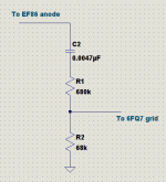
If you want to keep and tweak the somewhat unique (for a valve guitar amp) Baxandall tone controls you have now, you also have the possibility of inserting a notch filter somewhere in the signal chain. It could be fixed (or adjustable with a trimpot). If there is room for a front panel switch, you could even make it switchable.
The attached image shows a notch-filter circuit I originally posted in a different diyAudio thread. This could go between two of the gain stages in your amp. (R1+R3) is a 1 meg pot - could be an internal trimpot you set to taste, if you don't want an external knob. The caps can also be changed to put the notch where your ears prefer it. (I like 800 Hz, to my ears that takes away a little harshness and makes guitars sound nicer. But not every guitarist wants a guitar to sound "nice"!)
-Gnobuddy
Gnobuddy,
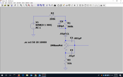
Upon further research yesterday and today I believe I agree LTSpice is the best way to go. I started down the youtube tutorial rabbit hole and was able to recreate the bass half of my tone stack (screen shot attached below). I should be able to recreate the treble half too in order to simulate the whole TS circuit, but now my current problem is how to simulate the triode that is boosting the signal between the two pots. Is there a good way of doing this in LTSpice that you are aware of?
I think the idea of replicating the Deluxe Reverb tone stack is growing on me the more I look into it. It's a decidedly mid scooped sound but a little less so than the other blackface amps of the era since the mids are fixed with a 6.7k resistor instead of an adjustable pot. I like how this keeps things from getting too hollow sounding but still allows a mid scoop that plays nice with all the overdrive pedals out there that offer mid humps when engaged. I understand the Fender TS loads down the signal a lot more than a James TS, but I think we have plenty of gain stages with which to recover signal before it is sent on to the output tubes. If I were to do this where would you suggest placing the tone stack? I'm thinking between the 2nd EF86 and the 1st 6CG7 triode might be best?
At that point I stopped using TSC altogether, because I wasn't sure I could trust it. Also, LTSpice was capable of simulating experimental or unusual tone control circuits that didn't exist in TSC.
Upon further research yesterday and today I believe I agree LTSpice is the best way to go. I started down the youtube tutorial rabbit hole and was able to recreate the bass half of my tone stack (screen shot attached below). I should be able to recreate the treble half too in order to simulate the whole TS circuit, but now my current problem is how to simulate the triode that is boosting the signal between the two pots. Is there a good way of doing this in LTSpice that you are aware of?
I think the idea of replicating the Deluxe Reverb tone stack is growing on me the more I look into it. It's a decidedly mid scooped sound but a little less so than the other blackface amps of the era since the mids are fixed with a 6.7k resistor instead of an adjustable pot. I like how this keeps things from getting too hollow sounding but still allows a mid scoop that plays nice with all the overdrive pedals out there that offer mid humps when engaged. I understand the Fender TS loads down the signal a lot more than a James TS, but I think we have plenty of gain stages with which to recover signal before it is sent on to the output tubes. If I were to do this where would you suggest placing the tone stack? I'm thinking between the 2nd EF86 and the 1st 6CG7 triode might be best?
Attachments
Wow, nice work! You got there much faster than I did....was able to recreate the bass half of my tone stack...
For your current purposes, all you need is something that buffers (isolates) the bass control from the treble control. This alone is sufficient to see both the bass and treble control curves. The absolute levels (insertion loss) won't be right, but the curves will still show you what the controls do.how to simulate the triode that is boosting the signal between the two pots. Is there a good way of doing this in LTSpice that you are aware of?
To make life easy, you could use one of the op-amps built into LTSpice as a buffer between bass and treble sections of the tone control. Or use a JFET, wired as a source-follower.
Optionally, you might want voltage gain as well; you can get this with an op-amp in the simulation if you want.
When you get a little deeper into LTSpice, you can actually find a vacuum tube LTSpice model, and throw it in there. Honestly, I'm not sure if that particular exercise is very useful, as math models for vacuum tubes tend to be very inaccurate in my experience, so they don't behave like the real thing anyway. More crucially, to understand the tone stack, you don't actually need a distorting valve stage in the middle of it!
I would suggest inserting the entire tone stack where your treble control is now. The reason is that EF86s, being pentodes, have much higher output impedance than 6FQ7 triode gain stages....Fender TS loads down the signal...where would you suggest placing the tone stack? I'm thinking between the 2nd EF86 and the 1st 6CG7 triode might be best?
In your circuit, the EF86 driving the bass control has a 68k anode load resistor. Pentodes have an extremely high internal anode resistance ("plate resistance"), so we can expect output impedance of the entire pentode stage to be not much less than 68k.
For comparison, a typical half-12AX7 triode stage with a 100k anode load has an internal anode resistance of maybe 70k. The output resistance of the entire stage will be 70k in parallel with the 100k external anode resistance, or roughly 40k.
Meantime, a 6FQ7 has an internal anode resistance of around 7k - 8k according to the datasheet I just looked at. This varies with operating point, but still, we can expect your 6FQ7 with 100k external anode load to have an output impedance of less than its internal anode resistance - just a few kilo ohms. It was born to drive heavy loads like Fender tone-stacks!
When you remove your bass tone control circuitry from in between the EF86 and 6FQ7, you should probably insert a pair of fixed resistors there, to cut down the signal by about the same amount as the bass control used to. Cut it down to roughly one-tenth as a starting point. Without this, you'll probably have much too much preamp gain, and lots of buzzy overdrive from the 6FQ7.
Incidentally, I've read several times that the way to get good guitar tone from valves is to run the signal through several valves, cutting the signal strength back down in between each pair of gain stages. This allows each stage to add just a little sprinkle of distortion, rather than heavy buzzy overdrive. But all the little sprinkles add up, so you get good "valvey" tone by the time you reach the preamp output. I think this is already working for you in your amp - I quite liked the clean tone you were getting with your single-coil guitar.
-Gnobuddy
Thanks! It wasn’t easy, my brain cells are still smoking lol.Wow, nice work! You got there much faster than I did.
Good catch! I hadn’t even considered looking at the data sheet to figure output impedance for the dual triodes. Sounds ideal like you say.(6FQ7) was born to drive heavy loads like Fender tone-stacks
I will try to draw this all up tomorrow to make sure I’m doing it correctly, but should I just cut it out at the pot and attached .001uF and .01uF caps, or do I need to also cut out the 360k resistor and 100pF cap that are just before the bass pot in the signal chain? Looks like those are there as some kind of low pass filter to tame the high end maybe?When you remove the bass tone control circuitry...
That is actually a "bright cap" in guitar-amp terminology, but a rather subtle one that only kicks in above 2 kHz or so....do I need to also cut out the 360k resistor and 100pF cap that are just before the bass pot in the signal chain?
My guess is that it would be fairly subtle with a clean guitar, and might be unpleasantly harsh if you were to overdrive one or both of the EF86s at the start of the signal chain.
At any rate, I suggest starting out with the bare minimum: a cathode coupling cap to block DC, and a pair of resistors to divide down the voltage. The attached image shows suggested values, which I picked for reasonable impedance, attenuation, and lower cutoff frequency (bass). Let me know if that's not clear.
You can always tweak it if you don't like the result - say add a bright cap, or change the attenuation (insertion loss).
-Gnobuddy
Attachments
Let me know if that's not clear.
Nope, you answered both my questions perfectly. Just what I need to get started, thank you once again! I’ll post the new circuit revision sometime tomorrow. My fried brain needs to rest for the evening lol.
My brain's kinda fried tonight as well. Perhaps it's time for me to chill out with some good music or guitar-related YouTube videos. 🙂 Have you seen this one? (That Victory Kraken amp - the one the purple Tele's plugged into - sounds pretty good, no?) YouTubeMy fried brain needs to rest for the evening lol.
And you're very welcome - your current project is an interesting one, and I'm glad to help. By the time you get it sounding good, I think we'll both have learned some new things.
-Gnobuddy
I have seen it! I’m subscribed to Anderton’s YouTube channel for the gear reviews and for the British Humor lol. That amp is a tone monster, but so is Danish Pete’s purple tele. Also doesn’t hurt that he has the skills to make that gear sing lol. I’m also subscribed to That Pedal Show and JHS Pedals YouTube channels for the gear and the extra nerdy content, also a good bit of humor on those channels as well.Have you seen this one? (That Victory Kraken amp - the one the purple Tele's plugged into - sounds pretty good, no?)
Well I’ve definitely learned a ton since I started this project, so I’m glad to share any information that can be gleaned by anyone else doing a similar one in the future.... we’ll both have learned some new things
Good night and happy YouTubing 🙂
Okay, here's an updated schematic with the Tone-Stack changes I'd like to make. I used Gnobuddy's input for the placement of the new Fender style TS and also for the voltage divider where the old bass control was, in order to attenuate the signal coming from the 2 pentode stages. I took a crack at drawing in the new TS myself.
Am I alright copying in the TS just as it is in the old Fender blackface schematics, or do I need to adjust any of these values to cater better to this unique circuit? Any other changes I need to make or things I missed?
( I got the updated and simplified, printed schematic from another forum. Makes things much easier to see and edit than the old hand drawn schem. 🙂 )
Attachments
I suggest changing the 100k grid bias resistor that the treble pot feeds into - make that 1 megohm as usual. 100k will load down the tone-stack output heavily, and it won't behave as it did in the original Fender amp.Am I alright copying in the TS just as it is in the old Fender blackface schematics, or do I need to adjust any of these values to cater better to this unique circuit?
I didn't spot any other obvious problems, and I think it will work as drawn. Of course, you will probably still find it needs tweaking to suit your ears.
There is one oddball (cost-saving) feature that may turn out to limit your ability to voice the amp to taste: the shared cathode resistor and bypass cap between the two triodes (the ones book-ending the tone control circuit.)
The problem here is that you have no ability to shift the quiescent operating point of each triode by itself. Same problem with the cathode bypass cap values, so you can't tweak each stage independently. It's not a huge problem, and there's no need to change it if you are happy with the amp.
But if not, this is easily fixed. Simply wire pin 3 and pin 8 each with its own cathode resistor to ground. With half the current through each, you'll want to start with 3k for each one (rather than the shared 1.5k). 3k is a standard value in the E24 range, which would have been unusual when your amp was designed, but shouldn't be hard to find at Mouser or Digikey or Jameco these days.
You can then choose if you want to add cathode bypass caps on one or both triode stages, and you can also choose different values for them to voice the amp, if necessary.
Incidentally, there are already some E24-series values in your amp (360k, 51k), which was a surprise to me. Most old valve schematics I've seen used resistors from the cheaper, lower-tolerance E12 series.
-Gnobuddy
Good catch! I saw the 1M volume pot that comes after the TS in most Fender AB763 blackface circtuits but didn't think about it doing double duty as a grid bias resister for the next triode. It's the things like this that I can understand, but don't always know to look for.I suggest changing the 100k grid bias resistor that the treble pot feeds into - make that 1 megohm as usual. 100k will load down the tone-stack output heavily, and it won't behave as it did in the original Fender amp.
That should be an easy enough solution if needed 🙂But if not, this is easily fixed. Simply wire pin 3 and pin 8 each with its own cathode resistor to ground. With half the current through each, you'll want to start with 3k for each one (rather than the shared 1.5k).
So my understanding is that cathode bypass caps are a way of controlling gain in the triode, and also controlling which frequencies are gained? Lower bypass cap values produce a treble boost, while higher values begin allowing more gain in lower frequencies providing a warmer to deeper sound depending on how big the cap value is, right?You can then choose if you want to add cathode bypass caps on one or both triode stages, and you can also choose different values for them to voice the amp, if necessary.
Kinda sorta...Lower bypass cap values produce a treble boost, while higher values begin allowing more gain in lower frequencies providing a warmer to deeper sound depending on how big the cap value is, right?
Here's the thing. Inside the tube, there is an effective cathode resistance, just like the more commonly mentioned internal anode (plate) resistance. This internal effective cathode resistance has roughly** the value (1/gm), where gm is the transconductance of the tube.
**I've done a more exact calculation, but I don't know if you want to bother with the math. The internal anode resistance of the valve (ra), and its voltage gain parameter (mu) both have some effect on the value of the internal effective cathode resistance. But usually the dominant factor is gm.
Okay. For a 6FQ7, the datasheet gm is 2600 micro siemens. The reciprocal is around 385 ohms. Nothing is that exact in tube parameter world, so call it roughy 400 ohms. In effect, there is a 400 ohm resistor inside the bottle, between the cathode pin, and the actual metal plate (cathode) inside. (See, that's why I prefer to use "anode" rather than "plate" - there are four metal plates in one 12AX7, but only two are anodes!)
So suppose you now connect a 3000 ohm external cathode resistor, and put a bypass cap across it. At sufficiently low frequencies, the cap does nothing, and the triode "sees" 3400 ohms between its cathode and ground - the internal 400 ohms, plus the external 3000 ohms.
At sufficiently high frequencies, the cap essentially bypasses the 3000 ohm resistor to AC - it acts like zero ohms. The triode now "sees" only 400 ohms between its cathode and ground, and so has a higher voltage gain.
This means the triode has one (lower) value of gain at very low frequencies. It has a higher gain at very high frequencies. In between, there is a gentle ramp-up from the lower value to the higher value.
This is called a shelving filter. It has two "corner frequencies", one where the slope levels off into the low-frequency gain, and another where the slope levels off into the high-frequency gain.
The effect of changing the cathode bypass cap is to slide this entire shelving filter frequency response horizontally along the frequency axis - a smaller cap moves both corner frequencies higher, a bigger cap moves both corner frequencies lower.
What your ear actually hears depends on all sorts of things: the value of that internal cathode resistance (400 ohms for the 6FQ7), the value of the external cathode resistance (3k in our example), and the value of the cathode bypass cap.
At one extreme, if you used such a big cap that both corner frequencies were well below 82 Hz (lowest guitar frequency), it would make no difference at all to the sound if you doubled or tripled or quadrupled that bypass cap. The amp will sound the same whether you use 100 uF, or 1000 uF. Both are ridiculously too big.
At the other extreme, if you used such a tiny bypass cap that both corner frequencies were above, say, 5 kHz, again, your ear would hear little or no change you halved or quartered that bypass cap. You could use 47nF or 4.7nF, and there would be no change in sound. Both values are ridiculously too small.
Now you see why I shy away from descriptions like "bigger caps make the sound warmer". That's not always true!
But if you pick values that puts both corner frequencies where they matter - somewhere within the guitar's frequency range, say between 100 Hz and 1 kHz - then the value of the cap changes what you hear.
When I worked out the equations for the cathode bypass cap frequency response, I also wrote some Python code to calculate and display the corresponding frequency response. I think that code is still on my home computer (I'm at work now). If you want, I can run that code for the 6FQ7 parameters, and find out what sort of range of cathode bypass caps is likely to be useful in your amp. (It probably won't be the same values typical in amps using 12AX7 triodes, because gm,mu, and ra are all very different for the 6FQ7.)
-Gnobuddy
Last edited:
I do see, definitely too much going on here for generalizations. Thank you for the explanation, that was quiet helpful in bettering my understanding🙂Now you see why I shy away from descriptions like "bigger caps make the sound warmer". That's not always true!
That could come in very handy, but let’s wait to see if it’s necessary first. I’m going to see how the TS mod sounds with the shared cathode bias intact and then separate and make changes if necessary.If you want I can run the code for the 6FQ7 parameters
Unfortunately the amp is at a garage outside the city that I only drive out to on weekends (not enough room in my apartment in the city for this project at the moment, or a place I can safely crank the amp for testing either lol). I may not get out there this weekend though because of prior commitments, so it may be another week or so before I can get out to try these changes :-(
But I will update again once I have the work done. Slow and steady on this one, but I think it will be worth it in the end 🙂
You have my commiseration. 🙁...not enough room in my apartment in the city...or a place I can safely crank the amp
All my life I've loathed the thought of living in an apartment, and yet here I am, living in one. The cost of real estate in this part of British Columbia is now so absurdly high that I'm very lucky to have even that. Homelessness has been soaring in local cities in recent years, as even renting goes beyond the reach of many people.
I do have a few square feet of space for electronics tinkering, but with neighbours on three sides as well as above me, my guitar amps have to be muzzled down to about one-tenth of a watt output. It's hard to get any kind of good tone at such a low volume, but it's a challenge to which I keep trying to find a solution. 🙂
-Gnobuddy
What is the reason for 1M in signal path after 1st stage, and then 680k after next stage? That seems like a lot of noise generation.
What is the reason for 1M in signal path after 1st stage, and then 680k after next stage? That seems like a lot of noise generation.
Those are both doing similar work. When used with the grid leak resistors going to the following the stage it’s creating a voltage divide to attenuate the signal down before its amplified back up again. There is A LOT of gain coming out of those two pentodes. Also I think it’s good practice for the reasons Gnobuddy explained earlier. Chopping down the guitar signal at each stage and amplifying it back up again multiple times is often a great way to design a guitar amp circuit. All that cutting and amplifying does magical things to the guitar signal. Or at least so my research has told me, I’m definitely no expert here lol.
Given the high voltage gain of the input stage, I expect the 47k input grid stopper is the dominant source of thermal noise in the entire amp. (This is the case in most of the "classic" Fender valve guitar amp designs.)What is the reason for 1M in signal path after 1st stage, and then 680k after next stage? That seems like a lot of noise generation.
Keep in mind, the guitar itself has either a 250k or a 500k volume pot inside it. A pot at half-resistance has an effective source impedance one-quarter of its end-to-end resistance, so the guitar volume pot alone can add 67.5k or125k to the several-k resistive part of the guitar pickup coil's own impedance.
The bottom line is that there may be as much as 200k of resistor in series with the input of the amplifier, right where the signal is smallest. Most of this is inside the guitar, where we can't do anything about it. (You can't just lower the pot values in the guitar, because the guitar pickup coils themselves are high impedance, and can't drive anything smaller than 250k without damaging the guitar's tone.)
I'll bet my boots that this huge source resistance between guitar pickup and EF86 control grid is the dominant source of thermal noise in the entire amplifier. And there's nothing we can do about it!
Getting back to this amp, the EF86 input stage has a ridiculously high output impedance (not much less than 220k), and a ridiculously high voltage gain (because it was never designed for guitar, but rather for much smaller mic or tape head signals). The very high pot resistances were probably chosen by the designer to minimise loading effects due to the very high output impedance.
Incidentally, the 680k won't add much thermal noise at all - note that it effectively appears in parallel with the 68k grid bias resistor following it (Thevenin equivalent circuit). So the noise generated is less than you'd get from the 68k resistor alone. And that's far less than the effective input noise from the first stage of this circuit.
I think ElusiveMoose is taking the "one step at a time" approach to changing the amp, which makes total sense to me. The larger-than-usual pot values were stock, and have not posed an audible problem for him so far - at least, he hasn't said so. "Don't fix what isn't broken" may be a cliche, but it's still good advice!
-Gnobuddy
I grew up teaching myself "proper" audio engineering, in which one of the goals is to have extremely low THD (total harmonic distortion.) With modern solid-state electronics, this is now so universal, that for most purposes, we've become used to treating and thinking about all audio gain blocks as perfectly linear (no THD).Chopping down the guitar signal at each stage and amplifying it back up again multiple times is often a great way to design a guitar amp circuit. All that cutting and amplifying does magical things to the guitar signal.
Mathematically, with perfectly linear audio amplification stages (op-amps, say), it makes no sense at all to first divide down a signal with a pair of resistors, then amplify it back up. It's the logical equivalent of taking two steps back, and then two steps forward, putting you exactly where you started out.
So when I first saw this done in valve guitar amp schematics, it made no sense at all to me. I thought it was one of the many idiotic myths that have become an unfortunate part of all things related to electric guitars.
But I was wrong. Everything changes when you realize that gain stages in valve guitar amps are quite nonlinear, and we like them that way. Every stage adds distortion components to the original signal. Attenuating the output of the stage reduces both the original signal and the distortion by the same percentage - but the distortion isn't removed.
So the process of "amplify, attenuate, repeat" repeatedly adds some distortion to the signal, without letting the entire signal become ridiculously big. Now the math makes sense. Instead of "two steps back, two steps forward, repeat", its more like "two steps back, eat a spoonful of ice cream, two steps forward, repeat". You're back at the same place as before at the end, sure, but with a bellyful of ice-cream!
All of today's high-gain guitar amps use this approach. They are designed to add a huge amount of distortion at each stage, so that what comes out of the entire preamp is almost entirely distortion, with negligible amounts of the original guitar signal left.
Personally I'm not a fan of guitars distorted to the point where they sound like power tools rather than musical instruments. But it turns out that the "amplify, attenuate, repeat" approach also works very well if you add just a small amount of harmonic distortion at each stage. You end up with a signal that's still very recognizably a guitar, but with a richer timbre than the guitar by itself. Also richer than adding the same amount of distortion using just one or two nonlinear gain stages.
I haven't taken this approach beyond three gain stages myself, but I plan to. An experimental triode-pentode-triode preamp I built a while ago (with attenuators in between every two gain stages) had a sound I liked a lot - very clear and articulate almost-clean guitar tone, but with a distinct and musical timbre to it. But at the time I was focused on a different goal, so I made a mental note to follow up later, and pressed on.
-Gnobuddy
A 47k or 68k input grid stopper has been shown to just raise the noise floor of a guitar amp (obviously depends on the amp, and typically that would be a 12AX7 triode input stage), with the recommendation to reduce that to circa 10k to remove it as a noise contributor, whilst still retaining the other useful aspects of a grid stopper in that stage.
Just to clarify the
With respect to the amp at hand, there is no info from the OP on the gain achieved from each of the main amplifying stages, and what stages may be subject to clipping, so little in the way of what divider attenuation may be practical given the present location of pots, or what locations would benefit from an effective grid stopper (with respect to the signal being high enough for that stage to benefit from softening grid conduction). I haven't read through the parallel thread, so not sure if that info has already been presented by the OP. There are also many simple options for effectively doubling and halving section gains (compared to what the existing schematic shows) along the way, as well as doing some bass control, via adding/subtracting cathode decoupling.
Just to clarify the
aspect, that relates to a typical guitar volume pot at 50% resistance, or circa 80% rotation on an audio taper. Rotating the guitar pot to 100%, and using a nowadays accepted 10k stopper removes that additional noise source, so pedantically there is something that can be done (if that was the aim).And there's nothing we can do about it!
With respect to the amp at hand, there is no info from the OP on the gain achieved from each of the main amplifying stages, and what stages may be subject to clipping, so little in the way of what divider attenuation may be practical given the present location of pots, or what locations would benefit from an effective grid stopper (with respect to the signal being high enough for that stage to benefit from softening grid conduction). I haven't read through the parallel thread, so not sure if that info has already been presented by the OP. There are also many simple options for effectively doubling and halving section gains (compared to what the existing schematic shows) along the way, as well as doing some bass control, via adding/subtracting cathode decoupling.
- Status
- Not open for further replies.
- Home
- Live Sound
- Instruments and Amps
- Need PA amp conversion help