Hi Guys.
I could use the help of the crossover experts. I got a wild bug last week to build a pair of speakers. I got one done and don’t know exactly what to do with this crossover.
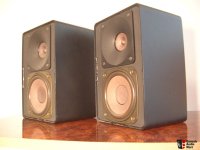
I started with an old beat up pair of RS Minimus 11s. I gutter the cabs an started sizing parts for the empty cabs. They are REALLY well built cast aluminum so are making a great starting point.
I installed the H45E horn, Dayton DT250P compression driver, SB Acoustics woofer, Peerless passive radiators (one on each side), and the Dayton 2 way crossover. I had the crossover, which crosses at 3.5khz which is the low cross point of the H45E horn.
It has been an exercise in stuffing 5 lbs into a 2lbs bag and the little bugger is heavy. I don’t have pix of the actual speaker but will post that today. But here are pix and links for all the parts.
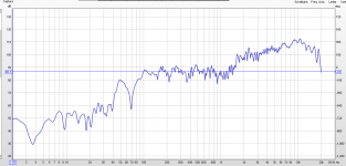
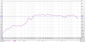
And a pic of the REW graph without any attenuation. I know I have to pad down the CD but don’t know what to do with the slope. If the CD was flat I could just pad it down, but, I think, the horn is making the CD response into a slope.
So, what would you do?
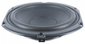
Passive Radiator
https://www.madisoundspeakerstore.c...s-830880-peerless-5.25-mini-passive-radiator/
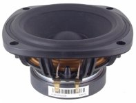
Woofer
https://www.madisoundspeakerstore.c...b-acoustics-sb13pfc25-08-5-paper-cone-woofer/
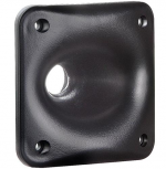
Wave Guide
Dayton Audio H45E 4.5" x 4.5" Elliptical Waveguide 1-3/8"- 18 TPI
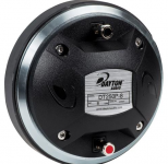
Compression Driver
Dayton Audio DT250P-8 1" Polyimide Compression Horn Driver 1-3/8"-18 TPI 8 Ohm
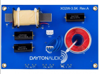
Crossover
Dayton Audio XO2W-3.5K 2-Way Speaker Crossover 3,500 Hz
I could use the help of the crossover experts. I got a wild bug last week to build a pair of speakers. I got one done and don’t know exactly what to do with this crossover.
I started with an old beat up pair of RS Minimus 11s. I gutter the cabs an started sizing parts for the empty cabs. They are REALLY well built cast aluminum so are making a great starting point.
I installed the H45E horn, Dayton DT250P compression driver, SB Acoustics woofer, Peerless passive radiators (one on each side), and the Dayton 2 way crossover. I had the crossover, which crosses at 3.5khz which is the low cross point of the H45E horn.
It has been an exercise in stuffing 5 lbs into a 2lbs bag and the little bugger is heavy. I don’t have pix of the actual speaker but will post that today. But here are pix and links for all the parts.
And a pic of the REW graph without any attenuation. I know I have to pad down the CD but don’t know what to do with the slope. If the CD was flat I could just pad it down, but, I think, the horn is making the CD response into a slope.
So, what would you do?
Passive Radiator
https://www.madisoundspeakerstore.c...s-830880-peerless-5.25-mini-passive-radiator/
Woofer
https://www.madisoundspeakerstore.c...b-acoustics-sb13pfc25-08-5-paper-cone-woofer/
Wave Guide
Dayton Audio H45E 4.5" x 4.5" Elliptical Waveguide 1-3/8"- 18 TPI
Compression Driver
Dayton Audio DT250P-8 1" Polyimide Compression Horn Driver 1-3/8"-18 TPI 8 Ohm
Crossover
Dayton Audio XO2W-3.5K 2-Way Speaker Crossover 3,500 Hz
Attachments
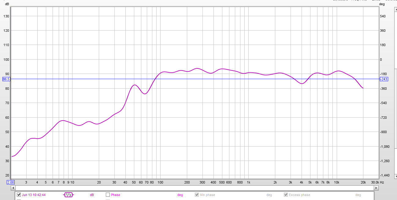
A couple of quick observations.
1. The deep null at 70hz is right at what WinISD said would be the f3 of that wood in that cab.
2. The crossover is at 3.5khz but the CD is not coming down until about 1.5khz. I don't understand either one of these things.
3. The measurement was taken after 2 minutes of the woofer playing straight out of the box. Both new woofers are hanging in my shop playing rap music. That should break them in well.
Last edited:
It would be helpful to show a xo plot with 3 curves: woofer, tweeter, combined so we can see where to shape it.
I suspect the CD/waveguide is so darn sensitive that is why you don't see it coming down until way below 3.5k. It's probably a 12dB/oct XO so at 1.75kHz it's only 93dB sensitive (down from ~105dB?). Still more than your woofer can provide. It will need lots of padding or maybe a resistor divider network to get a circa -20dB cut to match the woofer. Try a 4.7ohm and 0.47ohm 10w cement resistors in series from tweeter out of XO to ground (0.47ohm to ground) and connect tweeter to middle between two resistors. That should give -20dB (10x) attenuation.
I suspect the CD/waveguide is so darn sensitive that is why you don't see it coming down until way below 3.5k. It's probably a 12dB/oct XO so at 1.75kHz it's only 93dB sensitive (down from ~105dB?). Still more than your woofer can provide. It will need lots of padding or maybe a resistor divider network to get a circa -20dB cut to match the woofer. Try a 4.7ohm and 0.47ohm 10w cement resistors in series from tweeter out of XO to ground (0.47ohm to ground) and connect tweeter to middle between two resistors. That should give -20dB (10x) attenuation.
Last edited:
Hi X, good to see you again. This is the first speaker build after a long hiatus. I think I understand what you are describing but not sure. Are you talking about an L-pad with 4.7 from xo to tweet and the .47 across + and - ?
I'll go out and measure each driver now and post back in an hour of so.
Cheers, Dennis.
I'll go out and measure each driver now and post back in an hour of so.
Cheers, Dennis.
Yes - that should suck the life out of that CD to get it to match the woofer. Which is telling you something - overly sensitive for this app. You might try a custom turned wood (I know you are handy with smooth wood shapes) waveguide or 3D printed one for a 2.5in full range like an SB65WB25AC-4. It will have about the same 90dB sensitivity as your woofer and lower distortion.
I don't have a lathe anymore and I am kind of stuck with what I have. I'll try the L pad and get back to you. Why do you think I am getting such a big dip at 70hz? Could it be the newness of the woofer?
Off to radio shack. I post new graphs as soon as I get the lpad in.
Off to radio shack. I post new graphs as soon as I get the lpad in.
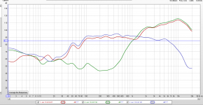
Here is separate woof (Blue) tweet (Green) and both (Red)
The woofer is not falling off fast enough either. Flat though - is there a peak without xo near 6k? I wonder if that is pushing it up?
The CD may be just perfect with -20dB (10x cut).
At this point it looks like the Dayton Xo is not going to work given how the low pass is somewhere up around 6k.
Are you amenable to making a custom XO with help from others here? Will need to measure each driver full range and combined in parallel without touching mic or speaker. Get us FRD files and impedance sweep ZMA files. Xsim or PCD can probably get a decent result given what I see.
70Hz dip may be room mode (try moving to different spot). Or maybe some cancellation effect with passive radiator. Where is the passive radiator located?
In thinking about it, if I flip polarity on the tweet and with the woof continuing flat for so far out, that region would be out of phase and might not sound good.
To answer your earlier question, yes, I am more than willing to do a sophisticated crossover on these. What I am hearing right now sounds very good and the woofs aren't even broke in.
To answer your earlier question, yes, I am more than willing to do a sophisticated crossover on these. What I am hearing right now sounds very good and the woofs aren't even broke in.
Well this looks much better than I expected. 🙂 The little 5dB dip at 4k is probably not all that audible - it may be just fine for you. The only way to fix that is to really work up a detailed study in a simulator to get the phase just right. Glad it worked out. This is just the 4.7 and 0.47 ohm padding resistors right?
Yes, well actually, it is two 8ohm resistors in parallel which worked out perfectly to 4.7ohms in line with the pos terminal and the .47 across the =/-
I would like to work up something better as I "think" I can hear a little less clarity in the region from 4 to 8khz where the woof is still flat out to 8khz or so. But you know how that is, if you know about it, I might just think I can hear it.
I think getting the woof on a steeper slope might help that.
There is good bass now, for its size, but I expect better when I get them burned in. I'll burn the woofs in outside the box while I make the cabs little works of art.
By the way, those files you asked for earlier, where do I find them? What are they?
Last edited:
![20160613_074012[1].png](/community/data/attachments/519/519826-5bf44e614a8e4303c63625870323924e.jpg?hash=W_ROYUqOQw)
The files are obtained by exporting the minimum phase frequency response as a text file in REW. You need to take the data a reference condition like 1m at 2.83v. The impedance ZMA curve is something you get by doing an impedance sweep of each driver by itself as mounted in box. If you have DATS speaker tester that is easy. With some wires and a resistor you can make one to use with REW (in help file).
The frequency response txt file is called the FRD file. The impedance text file is called the ZMA file. With those two and info on exact spacing of drivers and where mic is located allows designers to develop a xo for this particular speaker system with diffraction and all.
The frequency response txt file is called the FRD file. The impedance text file is called the ZMA file. With those two and info on exact spacing of drivers and where mic is located allows designers to develop a xo for this particular speaker system with diffraction and all.
Thanks X. I'll try to figure that out and get them posted. I've been listening for about and hour and with my laptop EQ I've had to raise the top end to give it "air". Without it, they sound a little muffled.
For the time being would I use a notch filter or CD com filter to, essentially, bring up above 10khz?
For the time being would I use a notch filter or CD com filter to, essentially, bring up above 10khz?
Try experimenting with various resistor values - make the 0.47R a little bigger. There is a lot of attenuation to get it flat but there is falloff from 15k on up. Maybe try 0.68R, 0.83R or 1R. Or make the 4.7R smaller to 3R. Etc. it may give just enough boost to be pleasing without EQ. Ideally you need to have a -10dB notch to flatten the bump at 10k. Then only pad by 10dB not 20dB.
Probably easiest thing is adding a third 8R resistor in parallel with the two you are using to get the 4.7r. That is probably the right boost in treble without it chewing your ear off.
You might want to use this tool from Jeff B to get the minimum phase.
http://audio.claub.net/software/FRD_Blender/Blender.html
There is also a white paper on how the get the acoustic offset.
Last edited:
- Status
- Not open for further replies.
- Home
- Loudspeakers
- Multi-Way
- Need HELP with new build xover