Have a JL Audio 450/4 amplifier here on the bench which is completely unresponsive and shows no lights at all. I have read the few 450/4 posts on here and most of the other JL amp threads also but was not able to find a solution to my particular issue. The power supply fets for the front channel and their 47ohm resistors were defective and have been removed. All other power supply and output transistors are reading ok while mounted on the board. There was some corrosion on the bottom of the board but I had already cleaned it off before I read about that in some posts. Not sure if I have any vias that need repair.
Can I power up the rear channels alone with the ps fets for the front channels removed?
This amp is using IRFZ44R. Can I use IRFZ44N or another equivalent fet since IRFZ44R is unavailable in my area?
Using another post as a guide, I am posting the voltages present on the LM324M and the 6 points asked for concerning the remote turn on diode and associated resistors. I did notice that my readings on Pins 13 and 14 are different than most, 13 is low while 14 is high.
LM324M
1) 0.62
2) 6.66
3) 4.03
4) 12.31
5)6.69
6) 5.91
7) 11.04
8) 11.09
9) 6.61
10) 9.60
11) -0.00
12) 4.23
13) 1.65
14) 10.94
2203 resistor
1) 9.61
2) -0.00
2201 resistor
3) -0.00
4) 10.85
Diode from remote terminal
5) 11.53
Diode next to it
6) 6.65
Last edited:
See if you have a broken via in the circuit for pin 13.
Powering up only half of the amp shouldn't cause any problems.
Any of the Z44s should be OK.
Powering up only half of the amp shouldn't cause any problems.
Any of the Z44s should be OK.
Via for pin 13 has a good connection to two resistors left of the LM324, a 2204 and a 1003. On the common side of these with pin 13 I get 1.65. On the other side of the 1003 is 1.74 and the other side of the 2204 is 0.05.
The 100k should go on to connect to the emitter of an NPN transistor and the positive terminal an electrolytic cap, possibly 33uf.
I found those while tracing pin 13 and 14. What do I look for next? This amp is not as easy to tech through as most amps so I'm stuck. Have not come across any disconnected/damaged vias while tracing. Have no voltage at the vertical driver card for the PS FETs.
Do you read 0 ohms between that transistor/cap and pin 13? It appears that the connection is broken.
I get 0 ohms between pin 13 and the 100k and 2.2m resistor. The 100k resistor is between the cap and pin 13.
The 100k that is connected to Pin 13 is in parallel with another 100k and then connected to a 33uf cap. Both the cap and the parallel 100k have good ground connection on the other side.
The 2.2m (reads .241m in circuit and 2.18m when lifted) is connected to a large ZRZ component which is connected to a KIA78L transistor on its other side which also goes to pin 7 of an 8 pin opamp(3843B PEBD) located close to and connected to C524 small yellow capacitor and the black 100uf next to it. The ZRZ also connects to pin 8 of U607 (LM383M) and one side of two 10k and one 470 ohm resistors. The shared terminals of the ZRZ and the 2.2m also connect to a diode and transistor right next to them.
I have traced all the pathways but I don't know what I am looking for. Where does the voltage come from that goes to pin 13 as seen in other posts containing LM324?
Is the voltage I have on pin 14 as a result of the lack of voltage on pin 13, or is that another problem altogether?
Pin 14 is controlled by the voltage on pins 12 and 13.
The voltage for pin 13 comes from the NPN transistor. Have you located that transistor?
The voltage for pin 13 comes from the NPN transistor. Have you located that transistor?
The KIA78L base is connected to U600 and U500, the collector is 0 ohms with ground, and the emitter is connected to the ZRZ resistor, pin 8 of U607 and pin 7 of the 3843B among other things. Is this the NPN transistor that supplies pin 13 with its voltage?
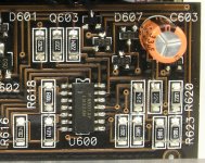
The 450/4 doesn't have these numbered like in the 300/4 but I think it is the ones next to the two ZRZ resistors since it is in a similar circuit as your pic. The larger transistor below it appears to be similar to 602 in your pic. There are two identical circuits side by side. The second set goes to the small yellow caps at the foot of the vertical PS driver boards numbered C527 and C628.
With no remote power, these transistors have 11.13v at their terminals. When remote power is applied, approximately 2-3v shows up on the output of the ones on the left but is quickly drawn down to 0.00. The ones on the right experience no voltage spike but climb from 0.2 to approximately 1.3v. The 2.2k resistor below them is directly connected to pin 14. Without remote power, this resistor has 11.13v passing through it. With remote power, the side connected to the transistors drops down to 6.32v. I lifted the 2.2k resistor and found that pin 14 has 11.11v on it with remote off, it drops to 0.00 and then climbs back to 11.07 when remote is applied.
Is this normal for pin 14 of an LM324M or is this ic damaged?
If you can show me where the supply voltage is supposed to be routed on the 300/4, I can probably figure out the differences in the 450/4 circuit. I just don't know how to trace back the turn on circuit.
Attachments

The ZRZ are 2.2 ohm resistors.
I think the components you need are to the right of what's shown in the photo.
I think the components you need are to the right of what's shown in the photo.
Thanks for the help thus far, I appreciate the time/knowledge/experience you are sharing.
I have pretty much traced these circuits thorough the amp, but I don't know where the +voltage that should be present on pin 13 should be coming from. The two transistors on the left attempt to supply voltage when turned on, while the two on the right remain unresponsive and unaffected. The voltage present on pin 14 briefly disappears but comes right back during turn-on.
So my questions are:
Where does LM324 pin 13 get its voltage from? (in the 300/4 if you are unsure of the 450/4)
Is pin 14 supposed to output 11.13v with no remote voltage applied?
Is pin 14 supposed to output 11.7v after remote voltage is applied?
If I isolate pin 12 and 13(lift all connections) I assume pin 14 should have no output voltage on a properly working LM324?
1. The emitter of Q603 in the 300.
2 and 3. When the amp completes it's initial startup cycle, pin 13 will be driven up by Q603 (in the 300) which will drive pin 14 down.
4. With all pins simply disconnected, the operation isn't certain.
2 and 3. When the amp completes it's initial startup cycle, pin 13 will be driven up by Q603 (in the 300) which will drive pin 14 down.
4. With all pins simply disconnected, the operation isn't certain.
Still can't figure out what's going on with pin 13 of the LM324. I have removed all kinds of transistors and resistors trying to find the missing voltage. I have tried to compare the circuit for pins 1+2+3 with the circuit for pins 12+13+14 since they are similar. Still no success. I removed LM384 and tested all four corners and they all measure the same, no shorts or odd readings. I don't think LM384 is faulty. I just can't seem to figure out where the voltage that is missing from pin 13 is supposed to be coming from. Maybe if I understand better how it operates in the 300/4, I might be able to figure out the 450/4.
In the 300/4, where does Q603 source its voltage from?
What other components is the emitter of Q603 connected to in the 300/4?
In the 300/4, where does Q603 source its voltage from?
What other components is the emitter of Q603 connected to in the 300/4?
Since reinstalling the LM324 I have noticed some voltages changed. Not necessarily a good thing since I still have voltage on pin 14, but now have voltage on pin 13, but also have voltage on pin 1. Not sure what is good and bad in these readings. Hoping this makes some sort of difference even though the amp still doesn't power up.
LM324
1) 11.05
2) 6.88
3) 6.93
4) 12.20
5) 6.90
6) 6.82
7) 10.94
8) 7.36
9) 6.66
10) 6.92
11) 0.00
12) 6.75
13) 5.76
14) 10.98
220k resistor
1) 6.92
2) -0.00
220ohm resistor
3) -0.00
4) 10.54
Diode connected to remote terminal
5) 11.22
Diode next to it
6) 6.88
LM324
1) 11.05
2) 6.88
3) 6.93
4) 12.20
5) 6.90
6) 6.82
7) 10.94
8) 7.36
9) 6.66
10) 6.92
11) 0.00
12) 6.75
13) 5.76
14) 10.98
220k resistor
1) 6.92
2) -0.00
220ohm resistor
3) -0.00
4) 10.54
Diode connected to remote terminal
5) 11.22
Diode next to it
6) 6.88
Pin 13 has to go above pin 12 for 14 to toggle down.
The transistor driving pin 13 has its collector tied to the same source as pin 4 of the 324.
The transistor driving pin 13 has its collector tied to the same source as pin 4 of the 324.
Disregard the readings posted 2 posts ago, they are innaccurate. Pin 13 was not properly connected when I reinstalled the LM324.
Is there any other way that I can attempt to find the missing pin 13 voltage? Any other place that I can start and make my way back? I have lifted and removed all sorts of components and am no closer to understanding what is going on here.
Is this missing pin 13 voltage the main(or first) reason why no leds are lighting and the amp being completely dead?
The low voltage power supply cannot start until pin 13 charges to higher than pin 12 and pin 14 goes low.
I don't think I can help any more unless I'd get a 450 in to repair.
I don't think I can help any more unless I'd get a 450 in to repair.
- Home
- General Interest
- Car Audio
- Need help with dead JL Audio 450/4