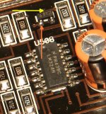
U503 is a KIA78L. I am only reading 1.2v on its output to supply the electronics. I removed it to test but one of the legs detached in the process. I substituted it with a 78L05 for testing purposes until I can get a replacement. Tested the 78L05 before installing it and it read 5.0v output. Installed it, but the power supply output only reads 0.80v. I am trying to trace the circuit to find out where it goes and to what components.
What can be causing the 5v regulated output to be pulled down?
What other components are supplied with this 5v regulated power besides both pairs of 74VHC112 and 74VHC132?
What can be causing the 5v regulated output to be pulled down?
What other components are supplied with this 5v regulated power besides both pairs of 74VHC112 and 74VHC132?
The input pin climbs to almost 12v when remote is applied but then starts to drain downwards after that. VThe middle pin is a good ground. The output pin never goes higher than 1.2v.
Didn't you find that pin 14 was responsible for that 12v source?
If so, does 14 stay near1v while the voltage on the input pin of the 5v regulator drops?
If so, does 14 stay near1v while the voltage on the input pin of the 5v regulator drops?
The problem is definitely in the 5v regulated circuit. Pin 14 measured .85v while powered up without moving, with the 5v regulated output leg attached or detached. I lifted the output leg of the 5v regulator and applied remote power and the voltage on the leg was 4.96 steady, while the 12v on the input leg dipped to the low 11v range and very slowly went down. With the output leg attached to the 5v regulated circuit, the output leg reads .75v while the input leg still dips to low 11v range and descends slowly. Something in the 5v regulated circuit is gobbling up the 5v.
If the input to the regulator is dropping to 0v, you may have a problem with the control circuit.
If the 5v regulator is shutting down, try inserting a low value resistor (5-10 ohms) in series with the output leg. That should allow it to remain on. Then you can try to find the defective component. Freezing the components on the 5v line and looking for the one to defrost first may be the easiest way to find the defective component.
If the 5v regulator is shutting down, try inserting a low value resistor (5-10 ohms) in series with the output leg. That should allow it to remain on. Then you can try to find the defective component. Freezing the components on the 5v line and looking for the one to defrost first may be the easiest way to find the defective component.
Connected a 10ohm resistor in series to the output leg of the 5v regulator. Tested before connecting to the 5v circuit and got 4.96v. Connected it to the 5v circuit and only got .85v in the circuit after the resistor, and 2.16v before the resistor. The supply voltage dropped slowly to about 10.45v and stayed there before I disconnected the remote power.
What components are supplied with power from the 5v circuit?
I know the two 74VHC112 and two 74VHC132, but I don't know what else... I am placing a parts order soon and would like to order a complete set of replacement parts for this 5v regulated circuit at the same time.
What components are supplied with power from the 5v circuit?
I know the two 74VHC112 and two 74VHC132, but I don't know what else... I am placing a parts order soon and would like to order a complete set of replacement parts for this 5v regulated circuit at the same time.
I don't know. Check continuity from the 5v line to the power supply pins of all ICs and nearby capacitors.
Do you know what is connected to regulated 5v in the 300/4?
Could the problem be a defective IC or capacitor that is pulling down the 5v?
Once the output driver cards are powered up, and the +43v and +15v are powered up, the next step is to power up the logic ICs and the PS driver cards? Or is there something else that happens during or before that?
Where does the LED display receive it's power/signals from?
Is there any other possible cause for the 5v not reaching full power?
1. I've never had to find all components connected to the 5v line. It would likely take you less than 3 minutes to do what I suggested.
2. Yes
3. Everything powers up except the power supply boards. Then after a short delay, the power supply boards are enabled by pin 1 of the 324 going low.
4. I don't know.
5. I don't know.
2. Yes
3. Everything powers up except the power supply boards. Then after a short delay, the power supply boards are enabled by pin 1 of the 324 going low.
4. I don't know.
5. I don't know.
Got this amp almost fully repaired. Changed the 74VHC132 and 74VHC112 ICS for both power supplies. Changed the 6.8v zener diode on the driver board for the front channel that was blown. I now have rail voltage for both channels +/-28v and +/-38v and all four channels play audio but not yet fully tested for clarity. There was no illumination from any of the led lights but I touched up and resoldered some of the transistor and resistor joints in the area between the power input terminals and the 5v regulator.
QUESTION: The green power led now lights up but the red thermal led is also illuminated. How do I diagnose whether I still have an actual problem or whether I just need to replace a component or resolder/restore a connection?
QUESTION: The green power led now lights up but the red thermal led is also illuminated. How do I diagnose whether I still have an actual problem or whether I just need to replace a component or resolder/restore a connection?
After touching up the solder connections for the LED circuits on the driver boards, how many are lit/unlit?
All 3 LEDs are lit on all four driver boards. All incoming/outgoing voltages on all four boards are identical so I don't think I have any problems in the audio section. Both rail voltages are closely matched and there is no excessive current draw at idle so I don't think I have any power supply problems. I have only played audio to a 6x9 test speaker, and at low level but audio is not distorted.
The remaining issue was that the status led panel showed no function even though the amp was turned on and idling with stable rail voltages. I traced the circuit back for the green led wires and touch up most of the transistor, resistor and diode connections that lead to the area around the LM324, the power terminals and the 5v regulator. After doing this, the green led started to work when the amp powered up, but the red ledbis constantly illuminated also.
I need to know how to troubleshoot the protection circuit to determine whether there is an actual fault, if there is a defective component or connection, etc. Not sure whether the amp would produce unhindered full output, or whether it is in protection and would reduce output, or if the led is inadvertently illuminated. Thanks.
Has anyone diagnosed a thermal light fault on a JL Audio slash amp before?
I plan on tracing back the circuit from the led backwards bit that is going to be a time-consuming shot in the darkness... I don't really know what I am looking for.
I plan on tracing back the circuit from the led backwards bit that is going to be a time-consuming shot in the darkness... I don't really know what I am looking for.
I've never had to trace it on this amp and have never had a thermal light on that left the amp operational.
From what I remember (vaguely) is that thermistor drives an NPN transistor, then a PNP transistor then goes to the power supply board.
Maybe someone else can give more definitive information.
From what I remember (vaguely) is that thermistor drives an NPN transistor, then a PNP transistor then goes to the power supply board.
Maybe someone else can give more definitive information.
I don't think that it goes to any ICs on the main board. As far as I know, all of the LED drive is on the main board.
Slight setback with this amplifier. While trying to investigate the thermal light issue there was a slip of the VM probe and the amplifier no longer powers up. No low voltage supply operation either. I will post the voltages on the LM324 in hopes that the fault could be diagnosed quicker.
LM324
1) 12.4
2) 1.05
3) 8.29
4) 12.64
5) 1.02
6) 11.33
7) 0.00
8) 0.59
9) 12.64
10) 8.28
11) -0.00
12) 8.18
13) 0.53
14) 12.4
LM324
1) 12.4
2) 1.05
3) 8.29
4) 12.64
5) 1.02
6) 11.33
7) 0.00
8) 0.59
9) 12.64
10) 8.28
11) -0.00
12) 8.18
13) 0.53
14) 12.4
- Home
- General Interest
- Car Audio
- Need help with dead JL Audio 450/4