I have a Marshal 8008 power amp that I have owned about 15 years after about 4 years ownership it stopped working. I opened it up saw blown fuse (can't remember which were gone) tried replacing the fuse but I remember it just blew again so I put it in the loft and forgot about it as I knew nothing about electronics then.
I've been building my own effects pedals for about a year now and remembered the amp the other day, and now that I know a bit more I thought i'd have a go at repairing it. I've only worked on pedals so I am completely new to working on amps.
Image of internal layout:
Link to schematic:
http://www.amparchives.com/Amp Arch...Rack Mount Power Amp/rackmount_2x80w_8008.pdf
What I have done so far:
Pulled all 6 transistors on the heatsinks and tested them, found a short on the T64 /T65 pair on channel A. So I swapped them out for TIP 142 /147. (Although I did completely forget and bought them in a smaller package size than the original output transistors.)
Plugged a guitar into Input A and a 4ohm cab into Output A, turned guitar volume to 0 and amp volume to 0 and turned it on. The output transistors on channel A blew instantly and were smoking so I turned it off quickly. None of the fuses blew though.
So I lifted the base leg of all of the smaller transistors and tested those, all of them were fine.
So I removed the rectifier and tested that and it was fine.
While the rectifier was out I tested the voltage reading on the red and black wires on CON1 and got 57v reading.
Removed and tested the 2 big caps and both were fine so I put them back.
Does anyone have any Ideas what I should try next?
I've been building my own effects pedals for about a year now and remembered the amp the other day, and now that I know a bit more I thought i'd have a go at repairing it. I've only worked on pedals so I am completely new to working on amps.
Image of internal layout:
An externally hosted image should be here but it was not working when we last tested it.
Link to schematic:
http://www.amparchives.com/Amp Arch...Rack Mount Power Amp/rackmount_2x80w_8008.pdf
What I have done so far:
Pulled all 6 transistors on the heatsinks and tested them, found a short on the T64 /T65 pair on channel A. So I swapped them out for TIP 142 /147. (Although I did completely forget and bought them in a smaller package size than the original output transistors.)
Plugged a guitar into Input A and a 4ohm cab into Output A, turned guitar volume to 0 and amp volume to 0 and turned it on. The output transistors on channel A blew instantly and were smoking so I turned it off quickly. None of the fuses blew though.
So I lifted the base leg of all of the smaller transistors and tested those, all of them were fine.
So I removed the rectifier and tested that and it was fine.
While the rectifier was out I tested the voltage reading on the red and black wires on CON1 and got 57v reading.
Removed and tested the 2 big caps and both were fine so I put them back.
Does anyone have any Ideas what I should try next?
You need a methodical approach.
Initial testing would involve using a bulb tester to limit current and forcing the output stage to run at zero quiescent current. Also a basic check of the output stage components, in particular the low value resistors that may have been taken out by the fault.
Ultimately the fault is 95% guaranteed to be around the output stage but you can test and voltage check safely along the way. All easy stuff but is has to be done correctly.
It depends how keen and determined you are 🙂
Yes i'm a very determined guy.
Already getting the bits together to knock up a bulb tester as we speak.
If you can help me out with where to test etc that would be great.
Already getting the bits together to knock up a bulb tester as we speak.
If you can help me out with where to test etc that would be great.
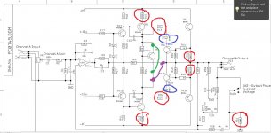
OK then...
I've just picked one channel to work on. We begin with a basic check of the resistors marked in red. Confirm the value of each is correct. If they read OK in circuit then that is normally good enough. If any read low or high in circuit then you must isolate (unsolder) one end and check again. The low value 0.33 ohms on the output transistor are quite critical to correct operation.
If they are all OK we now remove the two diodes in blue. This will disconnect the protection circuitry.
A shorting link (green) is added across TR5. This removes bias from the output stage.
Its quite likely that the driver transistors are damaged (TR2 and TR10). If they pass all the basic static junction tests and don't measure as leaky then at some point we have to power the amp up and see what we can deduce. (These transistors should be checked with at least TWO leads isolated. In particular check for leakage from collector to emitter using a high ohms range. Meter polarity is important for this check)
There are two ways of powering this up. First is with new output devices fitted OR we can power up with these removed and confirm the operation of the main circuitry. I would probably recommend without as a first test unless you have found a specific fault in all these tests.
If you remove the outputs then ADD the purple shorting link. This maintains connects the feedback network connection.
Switch on briefly and confirm there no obvious signs of distress.
Then measure and record the DC voltage on the purple link. It should be close to zero volts DC.
Those are the first steps and hopefully should reveal a problem somewhere along the way. And use the bulb tester at all times. Also no speakers connected.
Attachments
You may also want to check that the output jack is not shorting anything.. sometimes these can go bad and cause a short. Never connect/disconnect speakers from this amp while it's on.
Make sure the amp is in "Voltage" mode when youre doing tests. "Current" mode makes the (non existant) speaker part of the feedback network and will screw with things.
Make sure the amp is in "Voltage" mode when youre doing tests. "Current" mode makes the (non existant) speaker part of the feedback network and will screw with things.
I've found stressed output transistor can read okay on a diode tester, (2v) and blow up on real voltage. 85 v is dangerous to test with, so I hooked up 47kohms to a 12 v battery charger (17vdc with a capacitor on it). Short b to e, put a current meter in series with the charger, put plus on Collector (for npn) minus on b-e (opposite on pnp). Declaring transistors "bad" that leaked more current than new ones at 17v stopped them from blowing up when I put them back.
With the 47k resistor if you mess up and get it backwards it won't blow up anything.
I found even a 100 W light bulb in series with my 1.3KW amp wouldn't allow the voltage to build up enough to run the op amps, (+-16v) so I used a 1500 W room heater element. That kept the dies from blowing up to the ceiling through the steel case if anything shorted. The heater would crackle if anything was shorted and drawing too much current, so I didn't need to look at it like you would a light bulb.
Once the OT's go you may not be done just replacing them. I had 35 transistors bad, 14 diodes, 5 IC's, 3 thyristors, 12 resistors and 5 ceramic capacitors bad. The cost wasn't that bad except for output transistors and emitter resistors, I used the surviving MJ15024-25's as TO3 drivers, bought a couple of IC's and MJ15032-33 predriver transistors, and the rest came from dead PCAT power supplies.
Last edited:
Update:
- All diodes on the board seem good.
- All the resistors are good
- tested output transistors in circuit and found shorts between the collector and emitter on Channel A, channel B had no shorts.
I was testing resistors around the TL072 chip and found that on R3 in circuit I got 0.037 with the multimeter set to 2M, but on R4 it was counting up like a charging CAP. So I pulled one leg of R4 and it was good?
Does that mean anything?
Might mean the 100 pf cap C3 is blown on R3 or the land is burnt off or the solder joint is bad. You have to remove the TL071 to get readings. I lifted one lead of parts to measure if results were strange, particularly with R values above 2000 ohms.
Update:
- All diodes on the board seem good.
- All the resistors are good
- tested output transistors in circuit and found shorts between the collector and emitter on Channel A, channel B had no shorts.
I was testing resistors around the TL072 chip and found that on R3 in circuit I got 0.037 with the multimeter set to 2M, but on R4 it was counting up like a charging CAP. So I pulled one leg of R4 and it was good?
Does that mean anything?
That doesn't mean anything because all kinds of weird and wonderful things happen testing in circuit.
So the (already replaced once ?) output transistors are short. So two choices now... either fit new suitable devices and test again or power up and fault find with these removed as I outlined earlier.
I tested all the resistors out of circuit by lifting one leg, tested diodes by removing them completely, tested the small caps by lifting one leg.
yes I guess the tests around the chip could mean nothing as they were in circuit. all the components test good when you remove them from circuit. I just thought that because they were symetrical they would read the same and it might point to a problem with TL072.
yes I guess the tests around the chip could mean nothing as they were in circuit. all the components test good when you remove them from circuit. I just thought that because they were symetrical they would read the same and it might point to a problem with TL072.
you need to test TR5 out of circuit, as well as the resistor that goes between Q5's base and collector, and make sure it's not open. a shorted (or open) B-E junction on Q5 or that resistor being open will cause the bias to be wide open, which would instantly fry the outputs.
Last edited:
Hello Everybody, i have similar problems with this poweramp.
I have already replaced OT and bias/driver TR5. Tested the other transistors and replaced the burned emitter-resistors. When i turn on the amp (with the "purple connection" suggested by Mooly) only one half wave gets to the output.
Without the purple connection, very much current is drawn (smoking OT and mains fuse flashing). I am not sure whats the next step.
Should i remove the output transistors again (they havent smoked yet), to fix the problem? Or is it obvious what to fix/change?
thanks in advance!
ronny
Start from the beginning 🙂 and use a bulb tester. A bulb tester will prevent fuses flashing and failing and output transistors going up in smoke.
Alright. So I will start over again.
I have a variac with amp-meter. I only burned the circuit once. The next times I turned the supply down quick enough when I saw the amp-meter needle accelerating 🙂
I will post more soon.
I have a variac with amp-meter. I only burned the circuit once. The next times I turned the supply down quick enough when I saw the amp-meter needle accelerating 🙂
I will post more soon.
Hi,
With the setup recommended by mooly in the drawing, one check I will do it is removing the output transistors and power up the amplifier. Then read the voltage going to the speaker of the bad channel. If the drivers are OKAY then the reading should be close to zero. It maybe pos or neg depending of the problem with the drivers if there it is any.
With the setup recommended by mooly in the drawing, one check I will do it is removing the output transistors and power up the amplifier. Then read the voltage going to the speaker of the bad channel. If the drivers are OKAY then the reading should be close to zero. It maybe pos or neg depending of the problem with the drivers if there it is any.
Confirm. With light bulb or room heater in series with AC plug, input shorted, from the very beginning 3,2,1 of op amp should be about zero. Then if that okay center R28 & R44 should be about zero. Etc.
In my disater amp previous, the op amp input socket had a bad solder joint from the factory in 97 on the feedback pin, making it okay at cold start then cutting loose after a while and whaning everything to the rail and blowing up speakers, output transistors, drivers, predrivers. Look for something sneaky like that. Once the op amp has gone haywire, 50 v rated capacitors can blow, over wattage resistor can blow etc. Capacitors can read okay at 2 v meter test and short under rail voltage. Look for same voltage on each end power up on limiter when capacitor ends should be different.
I found power transistors measuring .550 v on diode test were okay, ones measuring .450 were over stressed and likely to blow in future. Of course a 12 v through 47 k resistor Vce with b-e shorted should read <1 ma through a meter, a better test than a diode meter test will give you.
In circuit power up, semiconductor junctions should be 0.6 v not zero, or more if back biased diode, and Vce of transistors should be more than zero if Vcb is .59 v or less,
Good luck.
Last edited:
- Status
- Not open for further replies.
- Home
- Live Sound
- Instruments and Amps
- Need help fixing Marshall 8008 power amp blowing output transformers