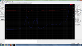
This is the graph from my WT3 and my DCM KX212's.
Wondering if anyone would like to hazard a guess what the crossover points are. Driver compliment is a pair of 12" woofers, a 6" midbass, and a piezo horn tweet similar to the one listed.
Pyle PSN1165 4.35" Piezo Horn Tweeter Pair 272-100
I have some ideas about it, but I don't want to taint your thought process. Thanks for any help.
...............................Blake
Attachments
Last edited:
What are you trying to do? Is the intent to try and do a better job? Just curious? The plot is dominated by the BSC and/or level matching with pole/zero at about 300 and 800, so it may not tell you a lot about the crossover. These look to be budget level, so I suspect it is quite simple.
I'm not sure that you are going to be able to devine anything about the crossover from the impedance plot of the speaker (I could of course be wrong 😉 )
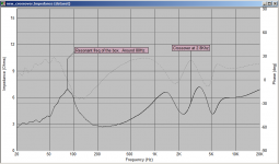
Just as an example see the attached impedance sweep of one of my MTM's. This is a 2 way with crossover frequency of 2.8Khz (4th order bessel accoustic slope).
About the only thing I can tell for certain from this is that the box tuning is pretty well smack bang on what my sims said it would be at 80Hz. Whether the peak in the phase at the crossover point is relevant or not I don't know, but certainly the impedance doesn't show anything to give away the crossover frequency.
The bumps in the impedance curve at around 1.3K and 3.5K are notch filters, so I guess that is another thing (with prior knowledge) that can be deduced from this impedance curve.
edit: what I would deduce from your impedance curve is that you have a bass reflex box tuned to around 38Hz, and that the presence of three impedance peaks quite likely means that it is a double chamber relfex setup. Apart from that I would be only guessing 🙂
Tony.
Attachments
Last edited:
My guess: the crossover of woofer to midrange in the impedance plot is at 650 Hz. The acoustic crossover is probably higher, maybe at 800 Hz. The midrange rolls off at 5-6 kHz, where the impedance starts rising. The piezo has a high impedance and is not visible in the impedance plot.
One chooses the frequency at which you want to cross over at, then using your test equipment you test the speaker at that frequency and note it's impedance and use that in the calculations.
Thanks for the replies.
Just trying to get an idea of crossover points, cabinet tuning, etc.
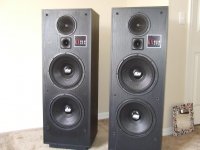
Found some info in about 5 minutes of searching (had previously searched for hours on these speakers and found basically nothing) which I include here. They are the KX212 models.
From the impedance and phase plots I also came to the conclusion that the cabinets were tuned at about 38hz . DCM lists the cabinet design as "Modified transmission line". They do have a folded line inside of the cabinet.
I also thought from looking at the graph that the crossover points were in the area of 600hz and 5000hz. The dip at 3000hz I supposed was some sort of notch filter.
A friend of mine had a set of the KX12's (single woofer) in the late 90's , I was in my early 20's and thought they were pretty awesome. 😛 I just picked these up a year ago for some basic jammers. They don't sound bad. I always thought they had pretty decent midrange and pretty decent bass response (not boomy).
Obviously the SPL (2.83V/1M) stats given by DCM are pretty optimistic at 105db. They wish. I would put them closer to about 95db.
Either way, just wanted to see what you guys thought. I remember for my friends set that we added more stuffing and changed the wire . Factory wire is pretty dismal, maybe 18-20ga , tinned, spade terminals , and just independent wires (not twisted or even zip cord). While we were swapping wires I noticed the crossover coils were of small gauge wire , and there were Bose-style light bulbs on the crossover . "PrestiDigital" Time Equalisation is what they call the crossover in these.
Thanks. Any thoughts are appreciated.
....................................Blake
Just trying to get an idea of crossover points, cabinet tuning, etc.
Found some info in about 5 minutes of searching (had previously searched for hours on these speakers and found basically nothing) which I include here. They are the KX212 models.
From the impedance and phase plots I also came to the conclusion that the cabinets were tuned at about 38hz . DCM lists the cabinet design as "Modified transmission line". They do have a folded line inside of the cabinet.
I also thought from looking at the graph that the crossover points were in the area of 600hz and 5000hz. The dip at 3000hz I supposed was some sort of notch filter.
A friend of mine had a set of the KX12's (single woofer) in the late 90's , I was in my early 20's and thought they were pretty awesome. 😛 I just picked these up a year ago for some basic jammers. They don't sound bad. I always thought they had pretty decent midrange and pretty decent bass response (not boomy).
Obviously the SPL (2.83V/1M) stats given by DCM are pretty optimistic at 105db.
They wish. I would put them closer to about 95db.Either way, just wanted to see what you guys thought. I remember for my friends set that we added more stuffing and changed the wire . Factory wire is pretty dismal, maybe 18-20ga , tinned, spade terminals , and just independent wires (not twisted or even zip cord). While we were swapping wires I noticed the crossover coils were of small gauge wire , and there were Bose-style light bulbs on the crossover . "PrestiDigital" Time Equalisation is what they call the crossover in these.
Thanks. Any thoughts are appreciated.
....................................Blake
Attachments
Last edited:
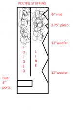
Just crunched some quick line length numbers. Internal cab length is about 40" , multiply times 2 for folded length is 80" , ports are about 6". That's 86". That's 157.7hz full wavelength, and 39.4hz at 1/4 wavelength .
......................Blake
......................Blake
Just remember it is the music spectrum or the power in the music that defines the crossover points not the speaker curves.
Just remember it is the music spectrum or the power in the music that defines the crossover points not the speaker curves.
Huh? The crossover points are a combination of the driver acoustic response and the electrical networks in the speaker system. They have nothing to do with the music, working equally well on noise as something more pleasant.
Hi guys,
I've taken the xover's out and as far as I can tell, this is how they are laid out.
What the heck do they have going on with the woofer crossover ? AFAIK , a 6.8ufd cap across will attenuate from about 600hz (approx) , but the one woofer is basically direct wired to the + terminal,while the other is connected via an inline coil, with the cap across the woofers + terminals.
Can someone splain it to me ?
The mid and tweet crossover look fairly straight forward to me,but I do have a few questions about those as well.
Midrange hi-pass cap is bypassed with a 1.8ohm resistor. So it would seem that they are creating a shallower rolloff than 6db an octave ? Basically about a 2db reduction in output below the caps crossing frequency of approx 600hz. So below 600hz the mid just runs as low as it can, at about -2db relative to the output above 600hz ?
Tweeter crossover has lite bulbs inline , I assume for power handling . The LCR network is a notch filter of some sort, and the coil closest to the tweeter's + terminal is to keep the amp from oscillating into the piezo's ever decreasing impedance with frequency rise ?
In summary, it appears to me that the tweet has a 12db/oct filter with additional components for power handling, response shaping, and stability.
The mid appears to have a very low-order/shallow hi-pass slope , with an 18db/oct low pass slope.
The woofer has some sort of bizarre network that I would like someone to explain to me.
The crossover PCB has copper traces , uses electrolytic caps (except for one 474k polyester? ) , and cheap ferrite core inductors with small gauge wire. The coil in the woofer circuit is larger than the others, but is still only 18ga , at best.
Wiring is individual strands of 20ga tinned stranded wire. Soldered to PCB and spade terminals on drivers end.
Thanks for any help.
...............................Blake
Attachments

Where have you been the last 50 years?
Building some very good speakers and taking a few physics classes, including a degree in electronics.
Bypass in midrange is baffle step compensation. Exactly as you say, a shelf.
The woofers are what we call a 3.5 system. Basically the second woofer in not really a full woofer, but restricted as they together would have a bit of a rising response. Very common.
Have to admit, I have never seen light bulbs in a circuit. I would have to guess thermally compensated resistors. Anyone with another guess? I have no experience with piezo tweets as basically, I can't stand them.
Below a certain power level, the bulb acts like a resistor.Have to admit, I have never seen light bulbs in a circuit. I would have to guess thermally compensated resistors. Anyone with another guess? I have no experience with piezo tweets as basically, I can't stand them.
The light bulb lights up above a certain amount of power, reducing the power to the tweeter.
Too much power, and the light bulb will burn out like a fuse before the tweeter if the circuit is properly designed and the bulb is within tolerance.
Bypass in midrange is baffle step compensation. Exactly as you say, a shelf.
The woofers are what we call a 3.5 system. Basically the second woofer in not really a full woofer, but restricted as they together would have a bit of a rising response. Very common.
Have to admit, I have never seen light bulbs in a circuit. I would have to guess thermally compensated resistors. Anyone with another guess? I have no experience with piezo tweets as basically, I can't stand them.
Ok, so midrange has a baffle step compensation. Am I understanding this correctly that the midrange basically runs down as low as it can go, with the only thing helping it as far as low frequency power handling being the inline resistor ?
Essentially it is running the resistor inline with the mid , thus reducing output until the point where the resistance of the 47ufd cap is less than that of the resistor (approx 600hz) ? So the midrange has no hipass per say, it is running it's full bass response ?
So the woofer with the "direct connection" and only the cap across it's terminals runs up to about 600hz, and then the cap starts filtering, while the other driver is connected via the coil and it is crossed over at a lower frequency ? Kind of like a "helper" woofer ?
The light bulbs in a tweeter circuit I have seen before, in pro sound and in Bose . They have a low DC resistance when measured, but as power increases, so does their resistance, and they also suck away some of the power . I believe they help absorb large transient spikes from damaging the tweeters, too.
So it looks like I have a lower crossover frequency for one woofer than the other, the midrange is essentially allowed to run it's full bass response with only a 1.8 ohm resistor inline , and the tweeter has a a bunch of stuff to make the piezo work properly. That sound about right ?
Thanks for your help. I appreciate it.
..............................Blake
Huh? The crossover points are a combination of the driver acoustic response and the electrical networks in the speaker system. They have nothing to do with the music, working equally well on noise as something more pleasant.
Maybe you should get some good books on crossover design.
balerit and tvrgeek
hey, you are both right about it, so cool it please will you, thanks

moderation
hey, you are both right about it, so cool it please will you, thanks
moderation
Originally Posted by tvrgeek
Huh? The crossover points are a combination of the driver acoustic response and the electrical networks in the speaker system. They have nothing to do with the music, working equally well on noise as something more pleasant.
So far, unlike your responses, tvgeek has offered some useful insight in to the design of the crossover used in Nihilist's speakers.
Without testing the individual pass bands the actual acoustic crossover points are only an educated guess. If one knew the impedance curves of all the components, one could narrow the guess down a bit more, but unit to unit variation still would make it only a guess.
What "good books on crossover design" do you find useful?
What is your native language?
Art
Huh? The crossover points are a combination of the driver acoustic response and the electrical networks in the speaker system. They have nothing to do with the music, working equally well on noise as something more pleasant.
Balerit,Maybe you should get some good books on crossover design.
So far, unlike your responses, tvgeek has offered some useful insight in to the design of the crossover used in Nihilist's speakers.
Without testing the individual pass bands the actual acoustic crossover points are only an educated guess. If one knew the impedance curves of all the components, one could narrow the guess down a bit more, but unit to unit variation still would make it only a guess.
What "good books on crossover design" do you find useful?
What is your native language?
Art
Below a certain power level, the bulb acts like a resistor.
The light bulb lights up above a certain amount of power, reducing the power to the tweeter.
Too much power, and the light bulb will burn out like a fuse before the tweeter if the circuit is properly designed and the bulb is within tolerance.
Yes, but I seriously doubt that is quite how they are being used. I have to suspect it is their increase in R with increase in I due to increase in Temp. I would also suspect they never "light up" and I doubt you could get them to blow without being really crazy. I could be wrong; DCM is noted for doing things out of the norm. Also note, light bulbs have quite a bit of inductance too, so that needs to be added to the crossover equation.
- Status
- Not open for further replies.
- Home
- Loudspeakers
- Multi-Way
- Need help figuring out crossover points