I found the network interesting so I decided to model it using my MW144's response (which have a peak around 4Khz). The attached shows two mw144's in parallel with no crossover components, and the blue is with just a 6.8uF cap and a 250 micro henry coil as per the schematic. The coil value was chosen at random, which makes the result even more suprising!
The notch is effectively taking out the peak. It is interesting because I have a notch in my crossover, but it is in series with Both the drivers, and has quite different values (actually this is probably because I didn't scale the impedance, the "driver" I used originally is actually both in parallel, so what I have just modeled has 1/2 the impedance to what it would in reality..
Tony.
That is interesting. Try it with a coil around 2MH please ? That's just my guess as to about how big the coil is in the DCM crossover.
Thanks Tony.
Thanks TVRGeek. I'll look into those links asap.
.........................Blake
Interesting! I doubled the impedance of my drivers so that it was closer to reality and the result is that it pretty much eliminates the baffle step. So my guess would be that it is being used as Baffle Step Compensation in your speakers (the sim result is only valid for my actual speakers which is all the more bizarre) but whatever value your coil actually is is no doubt tuned to your speakers 🙂 for what it's worth my baffle is 201mm wide.
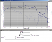
Attached is the comparison between raw drivers and with the notch using 2mH. I used a DCR of 0.345 ohms (14 gauge).
Tony.
Attached is the comparison between raw drivers and with the notch using 2mH. I used a DCR of 0.345 ohms (14 gauge).
Tony.
Attachments
Interesting! I doubled the impedance of my drivers so that it was closer to reality and the result is that it pretty much eliminates the baffle step. So my guess would be that it is being used as Baffle Step Compensation in your speakers (the sim result is only valid for my actual speakers which is all the more bizarre) but whatever value your coil actually is is no doubt tuned to your speakers 🙂 for what it's worth my baffle is 201mm wide.
Thanks for running the sim.
Why did you double the impedance of your MW144's ? Aren't they 8 ohm drivers ? The woofers in the DCM speakers are 8 ohms each, run in parallel for 4 ohms net.
..........................Blake
Attached is the comparison between raw drivers and with the notch using 2mH. I used a DCR of 0.345 ohms (14 gauge).
Tony.
Here is a set of very good and simple to understand papers on the subject. John explains things well.
True Audio's Loudspeaker Design Tech Topics Index
True Audio's Loudspeaker Design Tech Topics Index
I think a good way to find the xover points is to get from a friend an active crossover and listen to some music while changing on-the-go the crossover frequencies, this is a good way to know where to begin, after you just have to use this as your baseguide for building the crossover.
the danger of doing this is that you may give up of building an passive Xover and be seducted to use the active, that to me, IMHO, is always the better choice.
Mur,
Yes, handy. I keep a DCX on my bench for just that. However, the OP is trying to understand basic AC circuits and how they apply to passive crossovers. Not select crossover points.
I get more of a starting point for selecting the crossover points by looking at the CSD, non-linear distortion, breakup modes, and doing the power calculations on the drivers. The active crossover will not help in phase and position issues in the crossover region and it isolates ( good thing) you from the complex load a driver presents to the crossover.
Reason I doubled it was because the the impedance measurement I have is for both drivers in parallel. and the modeling I did for my own crossover treated them as a single driver 🙂
Yes they are nominally 8 ohms so doubling the value brought it back to square.
Tony.
Yes they are nominally 8 ohms so doubling the value brought it back to square.
Tony.
I measured the coil in the woofer section. It measured .686mh on the WT3.
These are not going to be hi-end(obviously), rather I am planning to use parts I have, and basically upgrade them on a budget. I will probably have to buy some parts, but plan on keeping it low budget. It will probably end up being a 6db/oct 3 or 3.5 way crossover .
One of the woofers surround is severely damaged , so I will be replacing all four surrounds (factory surround is much stiffer than the replacements from Parts Express) so they are matching.
While doing the surrounds, I plan on adding some venting under the dustcaps (peripheral vents around the coil former) , and possibly removing the bucking magnets. In every instance I have seen of drivers that are available in shielded and non-shielded versions, the addition of a bucking magnet for shielding raises the Qes (and resultant Qts) and reduces the BL. Seeing as I don't have any need for shielding, I am contemplating the removal of the bucking magnets to restore the Bl and Qts to their original specifications.
Adding ventilation to the woofers voice coil will reduce the Qms, and help driver linearity by helping keep the motor assembly cool.
I currently have all the drivers out of the cabinet, am adding bracing and damping material , and will be installing new crossovers . Pics to follow soon.
Thanks again !
...........................Blake
Last edited:
I think a good way to find the xover points is to get from a friend an active crossover and listen to some music while changing on-the-go the crossover frequencies, this is a good way to know where to begin, after you just have to use this as your baseguide for building the crossover.
the danger of doing this is that you may give up of building an passive Xover and be seducted to use the active, that to me, IMHO, is always the better choice.
I have used them in the past, and they are convenient for base lining the crossovers, however some I have used don't sound very good, muting a lot of the harmonics/overtones of the music.
I will probably use one my brother has for ballparking where I want to cross them over.
...............................Blake
So where did this end up Blake if you don't mind my asking?
I have 4 KX12's and curiously thinking about modifying them into 212's...
I have 4 KX12's and curiously thinking about modifying them into 212's...
I measured the coil in the woofer section. It measured .686mh on the WT3.
These are not going to be hi-end(obviously), rather I am planning to use parts I have, and basically upgrade them on a budget. I will probably have to buy some parts, but plan on keeping it low budget. It will probably end up being a 6db/oct 3 or 3.5 way crossover .
One of the woofers surround is severely damaged , so I will be replacing all four surrounds (factory surround is much stiffer than the replacements from Parts Express) so they are matching.
While doing the surrounds, I plan on adding some venting under the dustcaps (peripheral vents around the coil former) , and possibly removing the bucking magnets. In every instance I have seen of drivers that are available in shielded and non-shielded versions, the addition of a bucking magnet for shielding raises the Qes (and resultant Qts) and reduces the BL. Seeing as I don't have any need for shielding, I am contemplating the removal of the bucking magnets to restore the Bl and Qts to their original specifications.
Adding ventilation to the woofers voice coil will reduce the Qms, and help driver linearity by helping keep the motor assembly cool.
I currently have all the drivers out of the cabinet, am adding bracing and damping material , and will be installing new crossovers . Pics to follow soon.
Thanks again !
...........................Blake
Sorry for the delayed response, been busy with a lot of stuff, moved twice, changed jobs, etc.
Here's a summary of what I did. I didn't remove the bucking magnets from the woofers, they were on there VERY securely. I was able to remove them from the mids though.
1)I did use very simple DIY crossovers and 12ga wiring. The factory crossovers and wire are absolute garbage. I mounted the crossovers to a piece of plywood mounted to the bottom of the cabinet, on the inside.
2)I also added a bunch of bracing to the cabinets.
3)Lined the interior walls with cloth carpet padding (3/8" thick, looks like grey felt).
4)Added polyfill stuffing to both the front and rear sections of the cabinet.
5)Isolated the midrange by installing a piece of 8" diameter Sonotube (cardboard concrete form tube) between the front baffle board and the interior wall. I lined it with the same carpet padding and stuffed with polyfill.
6)I completely removed the port tubes and enlarged the vent opening by cutting out the material between the port holes, essentially making a larger oval shaped vent. I used 1/4" chicken wire over the vent to keep the polyfil inside.
7)I took the horn load off of the tweeter and cleaned up the plastic flashing left over from the molding process. There were several little plastic "flaps" in the horn throat. I used a new X-Acto knife and trimmed the flaps off and reinstalled the horn load.
8)I used "rope caulk" and damped the body of the piezo horn tweeter.
9)My woofers had bad surround, and I used the basic Parts Express 12" foam surround kit to replace the surrounds. It barely fits, as the woofer cones are kind of small diameter. There's only about 1/8" of cone touching the surround, so IDK if I would recommend using that kit. It seems to be ok, but I haven't had a lot of play time on them. The aftermarket surround is looser than the the factory surround, and that really seemed to make the bass much more dynamic, so in that respect I like the new surrounds.
10)When I refoamed the woofers, I removed the dustcaps and cut 3 or 4 (can't remember, think I have pics somewhere) holes in the woofers cone around the perimeter of the voice coil to vent the heat and pressure from the voice coil. I used Elmers glue on both sides of the cone around the holes to stiffen it up and prevent any rips/tears. The new dustcaps cover the holes, so the voice coil area under the dustcap just vents into the cabinet. A poor mans vented motor , if you will.
After I did the cabinet mods, I mounted all the drivers in the cabinet wired direct (no crossovers, had 4 pair of wires running out the ports for this test)and did sine wave sweeps and measurements with an SPL meter for each set of drivers, both woofers , mid by itself, and tweeter by itself to help decide my crossover points, etc. I'm very glad I did, because when I did bass sweeps, the cabinet made funny noises, and it lead me to find that the cabinet was loose and vibrating at certain frequencies. I poured glue in all the joints and screwed the cabinets together over several days . They weren't loose/leaking/vibrating after that.
I did all this over a stretched out length of time, but then I had to move so I wanted to get them together so I didn't have a bunch of loose parts when I moved. I got them together and listened to them for about a week before I moved, and they are currently still in storage. 😡
So, all that said, they utterly smoke the original setup. Much smoother upper mids and treble, bass is much punchier/more dynamic, seems deeper and fuller as well, but certainly not boomy. They're gonna need some tweaking to get them as good as they can be, but I was surprised how good they sounded as compared to stock.
I have pics saved in a camera somewhere. I'll take a look and when I find it I will post it in the thread.
If you wanted to get the majority of the performance without doing ALL the upgrades , rewire/crossover them, add polyfil, isolate the midrange (this REALLY cleans up the mids, keeps the mid from throwing wildly and actually improved/increased the bass from the woofers), damp the piezo tweeter housing.
These are all very cheap to do and are the brunt of the improvement.
Hope this helps, sorry if it was long winded.
..................Blake
Last edited:
So where did this end up Blake if you don't mind my asking?
I have 4 KX12's and curiously thinking about modifying them into 212's...
The KX-12 cabinets have more cabinet volume per driver than the KX212's have (which is good), but the line length is shorter, so they are tuned a bit higher.
My suggestion is to do the mods I listed above, but stack your cabinets like this. The main issue you are going to have is that the KX-12 woofers are 4 ohms, unless you have the Series 2 set which are supposed to be 8 ohms. You will want to look and see what the drivers are, as I have seen Series 2 woofers that are actually the same 4 ohm drivers as used in the Series I set.
............Blake
Attachments

Here's some pics like I promised. Sorry, I know it's been months. I haven't even been able to listen to them in months, they're still in storage. 🙁
https://www.facebook.com/blake.fole...5950.1073741828.1389643331&type=3&pnref=story
Couldn't get them to load here, so here they are. I lost a bunch of pics and data when I had computer hard drive issues. I'll take some more of the finished cabinets and post them later.
..............Blake
https://www.facebook.com/blake.fole...5950.1073741828.1389643331&type=3&pnref=story
Couldn't get them to load here, so here they are. I lost a bunch of pics and data when I had computer hard drive issues. I'll take some more of the finished cabinets and post them later.
..............Blake
https://www.facebook.com/media/set/...950.1073741828.1389643331&type=1&l=3d7e59b420
Can't edit my previous post, so here is a different link that might work betterer.
...........Blake
Can't edit my previous post, so here is a different link that might work betterer.
...........Blake
- Status
- Not open for further replies.
- Home
- Loudspeakers
- Multi-Way
- Need help figuring out crossover points