balerit and tvrgeek
hey, you are both right about it, so cool it please will you, thanks
moderation

No problemo
The new book from David Self on active crossovers is pretty good. A big jump from Lancaster. If you can go back to issue one of Speaker Builder, there have been many good pieces. Quite a few papers in the AES. Linkwitz has a lot of good information on crossovers, but note his solutions are active. I have not seen a contemporary book on passive crossover design I could call comprehensive. An opportunity I guess. I have not read all the books, so I could be missing a gem out there. Joe D'Apolitto's book Measuring Loudspeakers is a basic as without good measurements, you can't get very far in crossover design. The users manual for tools like Sound Easy can tell you a lot. Unfortunately, crossover design has a lot of art in it left. I have never seen anything written on network simplification to do things like combine BSC with the crossover. Why do some increase the first inductor, others the second?
I first encountered light bulbs in a speaker crossover when using Electro-Voice S-40 speakers as stand mounted stage monitors back in the 1980s, a Hi-Fi alternative to Galaxy Audio's Hot Spot.Yes, but I seriously doubt that is quite how they are being used. I have to suspect it is their increase in R with increase in I due to increase in Temp. I would also suspect they never "light up" and I doubt you could get them to blow without being really crazy. I could be wrong; DCM is noted for doing things out of the norm. Also note, light bulbs have quite a bit of inductance too, so that needs to be added to the crossover equation.
The first small blast of HF feedback burned all the light bulbs out.
At the time I thought the tweeters had fried, was glad to find it was only the bulbs.
We replaced the bulbs with resistors equivalent to the room temperature value of bulbs, and had no further problems.
Never blew any tweeters, and they still seemed to have flat response, so the inductance of the bulb did not seem to make much difference.
However, our test gear was only a 1/3 octave RTA then, often problems between ISO centers are impossible to detect.
Recently I was surprised to find a crossover I had designed using an RTA had a polarity reverse easily detectable using Smaart, though it appeared dead flat using the RTA 🙁.
I have replaced several burned out bulbs in various other designs. Some designs purposely put the bulbs in a position where they can be seen, so you have a visual indication that the tweeter is potentially being over driven.
Most of the designs using bulbs in the circuit are, shall we say, entry level, for folks that don't seem to recognize the sound of gross clipping, and the extra tweeter frying HF energy it can bring on.
Art
Last edited:
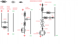
Look again at the woofer crossover portion. I'm still somewhat confused by it.
The one woofer is directly connected to the input terminals, but has a capacitor and a coil connected to (and supplying the input for) the second woofer.
The only way I see the first woofer having any high frequency attenuation is via the 6.8ufd cap , but in order for it so have any high frequency shunting effect , it first has to go through the coil of the second woofer to get to ground. So in effect the first woofer has a low pass consisting of a LC circuit shunting to ground, with the "L" of the LC circuit being the second woofers VC.
If that is the case , then the first woofer's high frequency response is barely attenuated at all, correct ?
I have WT3 impedance plots of all of the drivers, I'll post them up in a bit. Have to go run some errands.
Thanks again...........................Blake
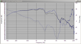
Here are the impedance traces of the drivers.
The tweeter has two sets of traces , the red and blue traces are just the raw piezo, and the lavender traces are with the crossover connected.
Again, thanks for any help understanding the woofer circuit better.
.............................Blake
The tweeter has two sets of traces , the red and blue traces are just the raw piezo, and the lavender traces are with the crossover connected.
Again, thanks for any help understanding the woofer circuit better.
.............................Blake
Attachments


I would expect the second woofer to be driven pretty much full range. I hope it has very low Q breakup very high. The woofers Le would be dominant.
More daring than a topless parallel resonant notch filter, but not as daring as an active crossover 😉.It is likely a bottomless parallel resonant notch filter.
Right.
Really, as we don't know the inductor size, we have no way to guess if this is a notch filter or a bandpass filter. I would really suspect this is a 3.5 way design and this is the bandpass for the second woofer.
Really, as we don't know the inductor size, we have no way to guess if this is a notch filter or a bandpass filter. I would really suspect this is a 3.5 way design and this is the bandpass for the second woofer.
Right.
Really, as we don't know the inductor size, we have no way to guess if this is a notch filter or a bandpass filter. I would really suspect this is a 3.5 way design and this is the bandpass for the second woofer.
You suspect what is the bandpass for the second woofer ? The 6.8ufd cap connected across the two woofers + leads ?
I don't understand how it could be a bandpass filter. AFAIK, a bandpass limits the low frequencies and the high frequencies , leaving the pass band/band pass.
You think they are limiting the low frequency response of one of the woofers ?
I'm going to run some frequency sweeps to get an idea of the spl/1w/1w of the individual drivers and go from there. I think I'll be installing new crossovers in these , as the factory units are pretty cheesy looking.
I would still like to understand what they are trying to accomplish with that cap across the woofers + leads.
...............................Blake
The L-C has basically no effect on the second woofer. It is going to be a notch acting on only the one.
200mH is about 135 Hz, 2mH is about 1500 if the woofers are anywhere near 8 Ohms. So says Spice.
200mH is about 135 Hz, 2mH is about 1500 if the woofers are anywhere near 8 Ohms. So says Spice.
The L is a lowpass for the one woofer, while the C is connected to both woofers + terminals. How could the L be a notch filter ? How could the cap not affect the direct coupled woofer (not the inductor coupled woofer) , it is going to do something to both woofers .
Confusion persists.
..........................Blake
Confusion persists.
..........................Blake
The L and C work together as a resonant circuit. Basically at some frequency, all the energy gets passed between them instead of being passed to the first woofer. Above that frequency all the energy goes through cap, below through the inductor.
Cover up the second woofer and look at it that way. That may help visualize. Again, I recommend downloading one of the Spice circuit simulators and play with it there.
Do a few Google searches on parallel and series filters.
Cover up the second woofer and look at it that way. That may help visualize. Again, I recommend downloading one of the Spice circuit simulators and play with it there.
Do a few Google searches on parallel and series filters.
The L and C work together as a resonant circuit. Basically at some frequency, all the energy gets passed between them instead of being passed to the first woofer. Above that frequency all the energy goes through cap, below through the inductor.
Cover up the second woofer and look at it that way. That may help visualize. Again, I recommend downloading one of the Spice circuit simulators and play with it there.
Do a few Google searches on parallel and series filters.
If above a certain frequency, all the energy goes through the cap, where does it go ? The only thing the cap is connected to is the woofers. It's not like it is shunting to ground. The only path to ground is through the woofers voice coils.
I understand that at a certain frequency, the cap is a low resistance path, lower than the resistance/impedance of the voice coil, but if the path only leads to another voice coil, then what is gained ?
I did look up series/parallel networks the other day, but I failed to see the correlation. I'll try looking again .
Where do you recommend I get a copy of Spice ?
Thanks ............................Blake
After thinking about what you said, I think I may have an idea.
Woofer"A" is wired full range, and always runs that way. Period.
Woofer "B" gets it bass frequencies through the inductor, up to the crossover point of the coil. Lets just make up a frequency here and say 200hz. So, up to 200hz, the coil offers a low resistance path to woofer "B". At 200hz, the response rolls off at 6db an octave. So at 600hz, we are -15db(2 1/2 octaves). Once we reach the frequency where the cap is tuned, lets say 600hz, it starts conducting , so at 1200hz the output of the cap is even , not plus or minus.
So woofer "A" gets bass help from woofer "B" , woofer "B" gets choked out for a while and then starts helping again above the crossover frequency of the cap.
Is that how you understand it ?
...........................Blake
Last edited:
Linear Technology - Design Simulation and Device Models
You are getting close. The L and C don't work independently, they are a tuned resonant circuit. It is a little hard to visualize. That's why it is easier to learn basic circuits in a lab course. Next best thing is a simulator. Of course, they did not have them when I went to school. Stick with it, you are doing what so many here won't. Thinking.
Parallel Notch Filter Designer / Calculator Help
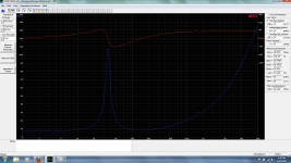
I found the network interesting so I decided to model it using my MW144's response (which have a peak around 4Khz). The attached shows two mw144's in parallel with no crossover components, and the blue is with just a 6.8uF cap and a 250 micro henry coil as per the schematic. The coil value was chosen at random, which makes the result even more suprising!
The notch is effectively taking out the peak. It is interesting because I have a notch in my crossover, but it is in series with Both the drivers, and has quite different values (actually this is probably because I didn't scale the impedance, the "driver" I used originally is actually both in parallel, so what I have just modeled has 1/2 the impedance to what it would in reality..
Tony.
Attachments
- Status
- Not open for further replies.
- Home
- Loudspeakers
- Multi-Way
- Need help figuring out crossover points