I have a device which was probably made in the 70s or 80s and it is completely made of discrete components except for the electronically balanced input which uses an NE5534N opamp. The other input methods are unbalanced (which is a straight-through wire connection) or transformer balanced. The overall spec for the amp includes 60V/uS slew rate for instance but the NE5534N spec seems to be around 13VuS. I suppose therefore that the 60V/uS was relating to inputs other than electronically balanced and I am wondering if there are other limitations being imposed by the NE5534N, and if there are ways to fix these?
I am aware that I could do things such as use the unbalanced inputs, buy some transformers and use those inputs. I am also aware that the changes might not be audible but would be interested in hearing what the possibilities are for this particular circuit (please see attached scan).
I am aware that I could do things such as use the unbalanced inputs, buy some transformers and use those inputs. I am also aware that the changes might not be audible but would be interested in hearing what the possibilities are for this particular circuit (please see attached scan).
Attachments
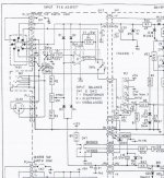
What an unusual circuit. The four diodes are simply clamps to protect against over voltage at the opamp inputs. What is unusual (to me) is seeing a CMRR trim pot which will be uniquely adjusted for each opamp and set of components. I would guess its adjusted for a null at the opamp output when applying two similarly phased input signals to each terminal of the balanced input. The 33pf and 10pf are for stability, the 33pf being applicable to the use of the 5534.
So looking at opamp swaps... the 10pf would almost certainly remain (possibly with some tweaking to suit the opamp), and the 33pf would go. The preset adjustment would need checking.
So looking at opamp swaps... the 10pf would almost certainly remain (possibly with some tweaking to suit the opamp), and the 33pf would go. The preset adjustment would need checking.
I don't understand what they have done.
Pin2 goes via a switch to 68uF to 15k+half of 1k and then splits, half signal goes to +IN the other half signal goes via half 1k and the other 15k to ground or chassis.
Pin3 goes via 68uF to 22k to -IN and thence through 22k||10pF to output.
The Pin2 and Pin3 loads are not balanced !
R1 should exactly match R2 and R3||cap should exactly match R4||C3
If R1=R2=21k5, then the CMRR adjustment would work. But this would require the missing cap to go wiper to ground.
Yes, the diodes are clamping diodes, for protection I guess. I have seen similar CMRR circuits (but not necessarily the same values or using pots) in data collector circuits for flight test instrumentation but not for audio.
What an unusual circuit. The four diodes are simply clamps to protect against over voltage at the opamp inputs. What is unusual (to me) is seeing a CMRR trim pot which will be uniquely adjusted for each opamp and set of components. I would guess its adjusted for a null at the opamp output when applying two similarly phased input signals to each terminal of the balanced input. The 33pf and 10pf are for stability, the 33pf being applicable to the use of the 5534.
So looking at opamp swaps... the 10pf would almost certainly remain (possibly with some tweaking to suit the opamp), and the 33pf would go. The preset adjustment would need checking.
Last edited:
The input stage is more than fast enough because the power amp gain multiplies the input slew rate. So the 60V/us is limited by the amp not the ne5534.
The Pin2 and Pin3 loads are not balanced !
That is puzzling me as well. The inverting input sees 22k input impedance, the non inverting sees 31k. That loading difference would cause an imbalance on any source component of significant output impedance.
Good point, I hadn't thought of that, thanks for the input.
The input stage is more than fast enough because the power amp gain multiplies the input slew rate. So the 60V/us is limited by the amp not the ne5534.
My thoughts...
I think its probably fair to say (look away now) that the design is a compromise in using one opamp to make a balanced/unbalanced convertor. It will work, but not optimally, any imbalance caused by source impedance will reflect as a change in overall level at the output. The CMRR adjust will work but is only valid for a given source impedance used to perform the adjustment. It was probably thought good enough... after all its not an instrumentation amp.
I think its probably fair to say (look away now) that the design is a compromise in using one opamp to make a balanced/unbalanced convertor. It will work, but not optimally, any imbalance caused by source impedance will reflect as a change in overall level at the output. The CMRR adjust will work but is only valid for a given source impedance used to perform the adjustment. It was probably thought good enough... after all its not an instrumentation amp.
But isn't it true that when the switch is in position U that the opamp is completely bypassed?
My thoughts...
I think its probably fair to say (look away now) that the design is a compromise in using one opamp to make a balanced/unbalanced convertor. It will work, but not optimally, any imbalance caused by source impedance will reflect as a change in overall level at the output. The CMRR adjust will work but is only valid for a given source impedance used to perform the adjustment. It was probably thought good enough... after all its not an instrumentation amp.
How about this for a possibility? Since the CMRR adjustment resistors seem to be an unusual feature for this type of opamp, maybe "normal" implementations didn't usually take account of CMRR, and just relied on the opamp doing its business properly. In this hypothesis maybe the designers found that the input characteristics aren't identical for +ve and -ve and had to adjust the external impedances accordingly? Just a thought, I can't see why else they would have done it this way.
But isn't it true that when the switch is in position U that the opamp is completely bypassed?
Yes, completely bypassed but look what it does. It shorts one of the balanced lines to ground and simply uses the other as the signal feed. That's not good practice either tbh, both from the viewpoint of shorting the source out, and also from introducing what could be substantial audio into a signal ground. That would depend on the current capability of the source component but its not good imo.
Even in its non optimal balanced form it can still reject common mode signals significantly. Another simulation.
Here we have the standard set up with balanced inputs having 180 degree phase shift as intended. I've also added a 600 ohm to the source impedance.

Now we reverse that phase shift and we get no output. Vin1 and Vin2 are superimposed on each other.

This is a close up of the output... not so much.

Now we add a 10 volts (yes 10 volts) 50Hz signal to both inputs. The output is essentially clean.

You are correct about the unbalanced input but AFAIK the -ve input would be o/c or connected to ground anyway in a pro system configured for unbalanced, in this case it seems appropriate to do what the designers did I think. The people configuring this would know what they were doing in this regard (I hope). I will look into your Spice pix, thanks a lot for doing the sims!
Yes, completely bypassed but look what it does. It shorts one of the balanced lines to ground and simply uses the other as the signal feed. That's not good practice either tbh, both from the viewpoint of shorting the source out, and also from introducing what could be substantial audio into a signal ground. That would depend on the current capability of the source component but its not good imo.
Even in its non optimal balanced form it can still reject common mode signals significantly. Another simulation.
Here we have the standard set up with balanced inputs having 180 degree phase shift as intended. I've also added a 600 ohm to the source impedance.
View attachment 536417
Now we reverse that phase shift and we get no output. Vin1 and Vin2 are superimposed on each other.
View attachment 536418
This is a close up of the output... not so much.
View attachment 536419
Now we add a 10 volts (yes 10 volts) 50Hz signal to both inputs. The output is essentially clean.
View attachment 536420
Last edited:
All of which doesn't look too bad to me, what was your impression? How accurate is the Spice sim of the 5534 would you say? Also do you think things would get better or worse if the values are equal for - and + inputs? I suppose the obvious guess would be that rejection would improve.
Yes, completely bypassed but look what it does. It shorts one of the balanced lines to ground and simply uses the other as the signal feed. That's not good practice either tbh, both from the viewpoint of shorting the source out, and also from introducing what could be substantial audio into a signal ground. That would depend on the current capability of the source component but its not good imo.
Even in its non optimal balanced form it can still reject common mode signals significantly. Another simulation.
Here we have the standard set up with balanced inputs having 180 degree phase shift as intended. I've also added a 600 ohm to the source impedance.
View attachment 536417
Now we reverse that phase shift and we get no output. Vin1 and Vin2 are superimposed on each other.
View attachment 536418
This is a close up of the output... not so much.
View attachment 536419
Now we add a 10 volts (yes 10 volts) 50Hz signal to both inputs. The output is essentially clean.
View attachment 536420
You are correct about the unbalanced input but AFAIK the -ve input would be o/c or connected to ground anyway in a pro system configured for unbalanced
Fair point. I've never used balanced connections and so am not totally familiar with standard practices and so on. What you say makes sense.
Its interesting to see it work in simulation and although the output looks clean, if you look at an FFT of the signal you can see the 50 Hz component. This is where the CMRR trim pot would be tweaked to minimise things.
Your welcome to the files if you want a play with LTspice 😉

All of which doesn't look too bad to me, what was your impression? How accurate is the Spice sim of the 5534 would you say? Also do you think things would get better or worse if the values are equal for - and + inputs? I suppose the obvious guess would be that rejection would improve.
You posted while I was typing 🙂
Erm... well simulation can be a mixed bag. I didn't use a model of the 5534 in the simulation, I used a standard model from the built in library which is actually a FET opamp of decent performance, quite similar to the OPA2604.
To get the best rejection would need the real world values tweaking. The sim results wouldn't apply because the models tend to be 'perfect' in many ways.
Here is a quick tweak making R4 in the sim 22k and R3 22.14k (derived empirically).

I think people deliberately changing from balanced to unbalanced (which would be rare) would use appropriate cables and select the Unbalanced setting on the switch, the circuitry would be correct for that situation. Without wanting to start any sort of cable discussion (due to the well-known opposing views on their quality) I think it possible that a lot of the differences in cable sound (probably very minor) are due to using unbalanced cables with differing characteristics between signal and return paths. Also all the music we listen to was made using balanced cables, and you can buy good quality balanced cables for reasonable prices (Neutrik connectors and Van Damme Studio grade cable for instance) knowing they are as good as those used in studios. Also all my gear is balanced (except the active crossover outputs so far) so I would be nuts to change it.
I would like copies of the files please! I'll get a copy of LT Spice downloaded.
I would like copies of the files please! I'll get a copy of LT Spice downloaded.
Fair point. I've never used balanced connections and so am not totally familiar with standard practices and so on. What you say makes sense.
Its interesting to see it work in simulation and although the output looks clean, if you look at an FFT of the signal you can see the 50 Hz component. This is where the CMRR trim pot would be tweaked to minimise things.
Your welcome to the files if you want a play with LTspice 😉
View attachment 536430
ref the whole balanced/unbalanced discussion I have completely changed my views over the last couple of years and all inputs should be balanced even if the source is unbalanced. Done right with (say) a THAT1200 on the front end you still get CMRR >80dB in all cases and, as you point out, forcing you to screened twisted pair cures all high end cable nervosa. It's a win on every front 🙂
I would like copies of the files please! I'll get a copy of LT Spice downloaded.
Here you go.
Attachments
I am not confident that the Designers did know what they were doing................ but AFAIK the -ve input would be o/c or connected to ground anyway in a pro system configured for unbalanced, in this case it seems appropriate to do what the designers did I think. The people configuring this would know what they were doing in this regard (I hope). .................!
It is over 20years since the Pin1 problem was fully explained and the solution given. Yet still we find "professionals" in the field of construction and assembly getting it wrong.
Balanced impedance connections requires the impedances at the Source and at the Receiver to be balanced. That requires NO CONNECTION to ground/earth/chassis for either of the signal wires.
the two 22k could be left as is.
The string of 15k+1kpot+15k must total the 22k+22k
If one wants to keep the CMRR adjustment @ 1k (or even 100r) then the two 15k must be changed to bring the string of three TOTAL to match the 44k.
The switching for the input transformer can take the output to the unbalanced signal return/ground of the amplifier. It is the connection that is balanced impedance.
But the INPUT to the transformer MUST be isolated from ground/chassis/earth. It's Pin1 that goes to Chassis and thence to Earth.
ref the whole balanced/unbalanced discussion I have completely changed my views over the last couple of years and all inputs should be balanced even if the source is unbalanced. Done right with (say) a THAT1200 on the front end you still get CMRR >80dB in all cases and, as you point out, forcing you to screened twisted pair cures all high end cable nervosa. It's a win on every front 🙂
I have no scientific evidence for this personally but it does seem very plausible. All the recorded music we hear is done this way. I also know people who have ditched expensive cables when they realised that ordinary balanced ones sound just as good. I must look into the THAT1200, I haven't heard of it before.
- Status
- Not open for further replies.
- Home
- Source & Line
- Analog Line Level
- NE5534N limitations for balanced input