Thanks a lot for all your input to this, it is very illuminating and welcome.
In the text you quoted I didn't intend to specifically say the designers knew what they were doing, I wrote that it was appropriate for the specific case of using unbalanced connections, and that the people configuring the systems for studios etc would know which connections they were using. I wasn't trying to make a general case for the quality of the whole circuit.
It seems that XLR Pin 1 in this circuit is taken to chassis in the correct version of the Pin 1 Problem (and this was 10+ years before Muncy so seems to be evidence of good design) but there is also a path to ground through the 15KRs and the pot. I'm (obviously!) no expert but isn't this the reason why semiconductor balancing isn't generally thought to be a pure form of balanced connection whereas transformers can be? In the doc here John H. Brandt Acoustic Designs on the subject it shows such a circuit as being a Typical Balanced Input and I think it is quite similar to the one I posted except for the diodes and the pots. It also has a ground ref. As you point out the resistor values do work out to the right totals.
What makes me wonder is why the designer would have chosen these values if they didn't work? It would have been easier to have used no potentiometer and just stick another 22KR in but maybe they really tested it and found out that this wasn't working, and therefore adjusted the circuit to make it work. Possibly this is due to the internal circuitry of the opamp? or the internal circuitry of one particular manufacturer's opamp at that time? It would be interesting to derive a test to see what is really going on, for instance the unbalanced input is just implemented with wire, would the apparently wrong resistor values induce some distortion that could be compared with that?
I am not confident that the Designers did know what they were doing.
It is over 20years since the Pin1 problem was fully explained and the solution given. Yet still we find "professionals" in the field of construction and assembly getting it wrong.
Balanced impedance connections requires the impedances at the Source and at the Receiver to be balanced. That requires NO CONNECTION to ground/earth/chassis for either of the signal wires.
the two 22k could be left as is.
The string of 15k+1kpot+15k must total the 22k+22k
If one wants to keep the CMRR adjustment @ 1k (or even 100r) then the two 15k must be changed to bring the string of three TOTAL to match the 44k.
The switching for the input transformer can take the output to the unbalanced signal return/ground of the amplifier. It is the connection that is balanced impedance.
But the INPUT to the transformer MUST be isolated from ground/chassis/earth. It's Pin1 that goes to Chassis and thence to Earth.
I have no scientific evidence for this personally but it does seem very plausible. All the recorded music we hear is done this way. I also know people who have ditched expensive cables when they realised that ordinary balanced ones sound just as good. I must look into the THAT1200, I haven't heard of it before.
http://www.thatcorp.com/datashts/THAT_1200-Series_Datasheet.pdf
Tomchr on this forum does sell boards that allow you to add to any amplifier to give a balanced input. If you look at the data sheet you can see that, even with a 600Ohm inbalance you still get 70dB CMRR at 60Hz. Also works up to pro levels if you like your interconnects hot!
The THAT product range is excellent for home audio. But because it is used in 'pro' stuff hasn't been given the welcome it deserves. After all, why use well engineered chips when you can come up with some arm wavy theory like most high-end manufacturers do 🙂
The resistors do not work out to the correct totals. nor do the matched pairs equals each other.................. As you point out the resistor values do work out to the right totals................
The circuit does not give a balanced impedance. It's wrong.
I've seen worse. In fact the power amplifier I am using at the moment has worse, just not ripped it out yet. Will try and find a cct to post tonight.
I was referring to the cct in the document I referenced in that same paragraph.
The resistors do not work out to the correct totals. nor do the matched pairs equals each other.
The circuit does not give a balanced impedance. It's wrong.
^ Agreed on all points. Sounds like a case for two 21k5 (E48/E96 series) resistors.The resistors do not work out to the correct totals. nor do the matched pairs equals each other.
The circuit does not give a balanced impedance. It's wrong.
Perhaps the CMRR trim was included to accomodate some sources without properly balanced output impedance - who knows what was still around in those days. Now of course with the unbalanced legs, you would have to retrim each time your source output impedance changed, even if both outputs were perfectly balanced! Plus, a pot always makes for a potential error source when it ages.
These days, just about nobody is using an input CMRR trim any more. You'll be making both legs as equal as you possibly can (precision resistors are a lot more common these days, which helps), and if that doesn't yield satisfactory CMRR and input noise levels (it usually does in high level applications), you'll go for an instrument amplifier topology, i.e. add two followers up front.
So you might even consider ditching/bypassing the pot altogether and using 4 matched ~22ks instead.
BTW, the NE5534 was about the latest and greatest in the early '80s, but I think optimum high-frequency CMRR is only reached when the compensation cap is upped to about 47 pF. At least I looked at the equivalent schematic and found that the input transistor collectors had a load of
1. 12k || 100 pF on one leg and
2. 12k || (40 pF + 12 pF) on the other.
So assuming my interpretation is correct (I guess next there'll be someone saying "no, you can't do that, you need to know voltage gains and impedances of where they're connecting to!!1"), that's a 48 pF imbalance. These parts do have issues with increasing high-frequency common-mode distortion, which tends to be connected to reduced high-frequency CMRR and hence input stage balance. Seems worth investigating in any case.
So there is absolutely no possibility that there could be differences in characteristics of the two inputs which, when added to the external resistor values, would cause the total of internal plus external to form a balanced circuit?
In that case it seems completely nuts to have done what they have done.
These amps were used extensively in broadcast and recording studios including the BBC and ITV. In fact the manufacturers were responsible for the amplifier packs that the BBC added to their passive speakers to make them active, it wasn't a backstreet operation. None of which changes the design but there is some pedigree to them, and it does seem an odd circuit to have come up with just for the sake of it.
I am considering changing the resistors to 22K since all evidence points towards it being a better solution but I think some CMRR testing might be a good idea at the same time, to see what the figures are for each version. Can anyone advise on the best circuit to do this?
^ Agreed on all points. Sounds like a case for two 21k5 (E48/E96 series) resistors.
Perhaps the CMRR trim was included to accomodate some sources without properly balanced output impedance - who knows what was still around in those days. Now of course with the unbalanced legs, you would have to retrim each time your source output impedance changed, even if both outputs were perfectly balanced! Plus, a pot always makes for a potential error source when it ages.
These days, just about nobody is using an input CMRR trim any more. You'll be making both legs as equal as you possibly can (precision resistors are a lot more common these days, which helps), and if that doesn't yield satisfactory CMRR and input noise levels (it usually does in high level applications), you'll go for an instrument amplifier topology, i.e. add two followers up front.
So you might even consider ditching/bypassing the pot altogether and using 4 matched ~22ks instead.
BTW, the NE5534 was about the latest and greatest in the early '80s, but I think optimum high-frequency CMRR is only reached when the compensation cap is upped to about 47 pF. At least I looked at the equivalent schematic and found that the input transistor collectors had a load of
1. 12k || 100 pF on one leg and
2. 12k || (40 pF + 12 pF) on the other.
So assuming my interpretation is correct (I guess next there'll be someone saying "no, you can't do that, you need to know voltage gains and impedances of where they're connecting to!!1"), that's a 48 pF imbalance. These parts do have issues with increasing high-frequency common-mode distortion, which tends to be connected to reduced high-frequency CMRR and hence input stage balance. Seems worth investigating in any case.
So there is absolutely no possibility that there could be differences in characteristics of the two inputs which, when added to the external resistor values, would cause the total of internal plus external to form a balanced circuit?
None whatsoever. The single opamp balanced to unbalanced stage is really just a bridge network if you think about it.
Try swapping the opamp in the sim for an LT1001 and make all the resistors 22k. Look at the residual 50Hz component.
One very real problem, even using matched resistors, is that the tolerance of the input coupling caps throw it all out of balance. Even a few uF imbalance causes the CMRR to deteriorate drastically because of the difference in reactance of the differing values. In days of old a tolerance for an electro would be +100/-50 %. These days you might be closer to -/+20%
This seems to be pretty unanimous here then.
An old-school analog designer (of many decades experience) I know said "The NE5534 +input may do something a bit odd and the resistor values restore the correct balance. Some of these audio ‘op-amps’ are more audio than pure op-amp if you see what I mean". But this is just a possibility rather than a considered opinion.
I haven't got round to the Spice yet but I will soon, thanks.
I was also wondering about those input caps. Are they really needed at all? If so could I change them for some other more sympathetic type? I can't even see if they are 6.8 or 68 uF!
None whatsoever. The single opamp balanced to unbalanced stage is really just a bridge network if you think about it.
Try swapping the opamp in the sim for an LT1001 and make all the resistors 22k. Look at the residual 50Hz component.
One very real problem, even using matched resistors, is that the tolerance of the input coupling caps throw it all out of balance. Even a few uF imbalance causes the CMRR to deteriorate drastically because of the difference in reactance of the differing values. In days of old a tolerance for an electro would be +100/-50 %. These days you might be closer to -/+20%
I wasn't sure over the caps either. 6.8 is more likely and I think there is a hint of a dot in the top one (but not that I could see in the other).
The 5534 was designed as an out and out audio device from day one but its still an 'opamp' at the end of the day and obeys the rules like other devices. The inputs do have two back to back diodes across them which can cause problems with fast slewing signals (but we are talking way and above anything audio). If the source component has no DC offset then the caps could in theory be linked out but in reality they are probably a good safeguard.
(You probably seen it already but if you click my signature line it gives a blow by blow account of installing LTspice)
If you change the 15k to 22k ±0.1%, then you must also remove the 1kVR adjuster. The VR is there to allow matching of the RATIO of upper side:lower side. That ratio matching is nearly as important as balance of impedance. But they should have done impedance balance first and then added ratio matching if their resistor tolerances required such.So there is absolutely no possibility that there could be differences in characteristics of the two inputs which, when added to the external resistor values, would cause the total of internal plus external to form a balanced circuit?
In that case it seems completely nuts to have done what they have done.
These amps were used extensively in broadcast and recording studios including the BBC and ITV. In fact the manufacturers were responsible for the amplifier packs that the BBC added to their passive speakers to make them active, it wasn't a backstreet operation. None of which changes the design but there is some pedigree to them, and it does seem an odd circuit to have come up with just for the sake of it.
I am considering changing the resistors to 22K since all evidence points towards it being a better solution but I think some CMRR testing might be a good idea at the same time, to see what the figures are for each version. Can anyone advise on the best circuit to do this?
Buy 5 off 22k ±0.1% and select the better matching 2pairs.
Those two pairs get inserted as PAIRS in the input side and the output side.
A 2000count DMM can just about resolve a difference of 1part in ~1950, if you set the CCS to 0.088mAdc (88uAdc) and the DMM to 1.999Vdc
You could increase the CCS current to 880uA and read on 19.99Vdc scale for a resistor dissipation of 17mW. Tempco errors will still be fairly low.
The capacitor imbalance becomes an issue at higher frequencies. This is especially the case for the RF attenuating capacitors that connect Line to Chassis at the input. But are there any RF attenuating capacitors? If so just remove the old ones and replace with matched pF values.
The big DC blocking capacitors (6u8F, or 68uF) would benefit from a loose matching of values but these have virtually no effect on CMRR in the audio band. They should begin to have impedance at frequencies <<20Hz and if chosen correctly <1Hz
Last edited:
6µ8 would align pretty well with typical sizing for a 22k input impedance in any case (my rule of thumb would be 10µ for 10k, i.e. RC = 100 ms or f3dB = 1.6 Hz).
I wouldn't say that the circuit is terribad, I mean, you can dial in a good amount of CMRR with the trim pot, and with shielded cable connections at line/pro level chances are nothing much would ever have happened, plus for really tough cases there still is the input transformer. So in practice it probably works well enough, it merely puts the electronically balanced input in a bit of a bad light.
I wouldn't say that the circuit is terribad, I mean, you can dial in a good amount of CMRR with the trim pot, and with shielded cable connections at line/pro level chances are nothing much would ever have happened, plus for really tough cases there still is the input transformer. So in practice it probably works well enough, it merely puts the electronically balanced input in a bit of a bad light.
I am considering changing the resistors to 22K since all evidence points towards it being a better solution but I think some CMRR testing might be a good idea at the same time, to see what the figures are for each version. Can anyone advise on the best circuit to do this?
Short both external inputs of the balanced socket together (at the socket) and apply a 50Hz test tone of quite high amplitude, say 1 volt RMS. Measure the opamp output on a scope and tweak the preset for minimum output.
Potential problems... the scope won't be sensitive enough to see the residual because you should be down in the 100uV peak to peak region. In that case you might need to construct a small battery powered amp to boost the opamp output.
50Hz may not be ideal because of internally generated hum etc. Maybe use an odd value of say 70 Hz.
Setting the preset this way will optimise the CMRR of the amp (which is all you can realistically do) but that doesn't take into account outside influences.
A standard preset won't have anywhere near the resolution to achieve a perfect null.
Increase the test frequency to 1kHz to check the CMRR where it is already down the slippery slope.
You could even try 10kHz to see how bad it is getting.
The VR ONLY sets the ratio. It leaves the balanced impedance unbalanced.
You could even try 10kHz to see how bad it is getting.
The VR ONLY sets the ratio. It leaves the balanced impedance unbalanced.
PS: (Please excuse me Mooly, you guys are posting too fast for me here right now...)
AndrewT, good point about caps actually. (And oops, overlapped posting.) Ditching the pot would be a good opportunity to inspect general layout, the physical size of the (-in) node should be as small as possible to minimise stray coupling.
You can think of a balanced connection as a Wheatstone bridge. CMRR for a given frequency is optimum if the following ratios of impedances are equal:
(Zsource(2) + Z(C2) + R2 + VR1 - Rtap(VR1)) / (Rtap(VR1) + R3)
and
(Zsource(3) + Z(C1) + R1) / (R4 || Z(C4))
with Z(Cx) = ( 1 / (j 2 pi f Cx) + ESR(Cx) +... ), Rtap = wiper position, and yes the expression generally is complex
Assuming we're above a few dozen Hz and well below the point where C4 becomes relevant and our source impedance is primarily resistive, this approximates to
(Rsource(2) + ESR(C2) + R2 + VR1 - Rtap(VR1)) / (Rtap(VR1) + R3)
and
(Rsource(3) + ESR(C1) + R1) / R4
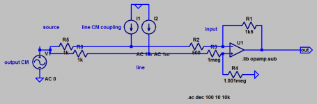
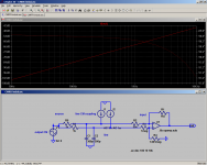
Funnily enough, optimum CMRR means optimum rejection for both output and line common-mode signals, which is not something you would expect right away if impedances on the two legs are different. In the attached example, electrostatic coupling (modeled by current sources) is suppressed just as well as a common-mode component on the output, despite the line being at ~333 ohms vs. ~1 kOhm.
Obviously all of this eventually blows up at higher frequencies as parasitic capacitance to ground/shield on the line (even if nominally equal) will have markedly different effects on the two legs. Actually Bill Whitlock has pointed out that capacitive coupling is not exactly equal because the colours of the wires are different, yielding subtly different dielectric constant and outer diameter, so possibly this was the reasoning behind 15k vs. 22k - though I have my doubts about this being repeatable enough to cast it into a circuit unless only one type of well-characterised cable were to be used (and always assembled the same way, which is starting to sound like quite a stretch to me).

EDIT: Yeah, look what happens if I add 2x 300 pF of shield coupling, not that unusual for a cable if some length.

It's much less severe for our case obviously, with CMRR remaining >70 dB to over 10 kHz, possibly still an issue when rejection of longwave / mediumwave signals or somesuch is asked for.
AndrewT, good point about caps actually. (And oops, overlapped posting.) Ditching the pot would be a good opportunity to inspect general layout, the physical size of the (-in) node should be as small as possible to minimise stray coupling.
You can think of a balanced connection as a Wheatstone bridge. CMRR for a given frequency is optimum if the following ratios of impedances are equal:
(Zsource(2) + Z(C2) + R2 + VR1 - Rtap(VR1)) / (Rtap(VR1) + R3)
and
(Zsource(3) + Z(C1) + R1) / (R4 || Z(C4))
with Z(Cx) = ( 1 / (j 2 pi f Cx) + ESR(Cx) +... ), Rtap = wiper position, and yes the expression generally is complex
Assuming we're above a few dozen Hz and well below the point where C4 becomes relevant and our source impedance is primarily resistive, this approximates to
(Rsource(2) + ESR(C2) + R2 + VR1 - Rtap(VR1)) / (Rtap(VR1) + R3)
and
(Rsource(3) + ESR(C1) + R1) / R4
Funnily enough, optimum CMRR means optimum rejection for both output and line common-mode signals, which is not something you would expect right away if impedances on the two legs are different. In the attached example, electrostatic coupling (modeled by current sources) is suppressed just as well as a common-mode component on the output, despite the line being at ~333 ohms vs. ~1 kOhm.
Obviously all of this eventually blows up at higher frequencies as parasitic capacitance to ground/shield on the line (even if nominally equal) will have markedly different effects on the two legs. Actually Bill Whitlock has pointed out that capacitive coupling is not exactly equal because the colours of the wires are different, yielding subtly different dielectric constant and outer diameter, so possibly this was the reasoning behind 15k vs. 22k - though I have my doubts about this being repeatable enough to cast it into a circuit unless only one type of well-characterised cable were to be used (and always assembled the same way, which is starting to sound like quite a stretch to me).
EDIT: Yeah, look what happens if I add 2x 300 pF of shield coupling, not that unusual for a cable if some length.
It's much less severe for our case obviously, with CMRR remaining >70 dB to over 10 kHz, possibly still an issue when rejection of longwave / mediumwave signals or somesuch is asked for.
Attachments
Last edited:
Don't I need to take account of source impedance for the CM injection?
This device is a power amp so has gain built in, I should be able to see the results of the (lack of) CMR on its outputs I think.
This device is a power amp so has gain built in, I should be able to see the results of the (lack of) CMR on its outputs I think.
Short both external inputs of the balanced socket together (at the socket) and apply a 50Hz test tone of quite high amplitude, say 1 volt RMS. Measure the opamp output on a scope and tweak the preset for minimum output.
Potential problems... the scope won't be sensitive enough to see the residual because you should be down in the 100uV peak to peak region. In that case you might need to construct a small battery powered amp to boost the opamp output.
50Hz may not be ideal because of internally generated hum etc. Maybe use an odd value of say 70 Hz.
Setting the preset this way will optimise the CMRR of the amp (which is all you can realistically do) but that doesn't take into account outside influences.
A standard preset won't have anywhere near the resolution to achieve a perfect null.
The 5534/5532 is optimal in terms of noise when used with source resistances of around 1KΩ. That's pretty small compared to what a polite line input impedance should be, so with the basic 4 resistor diff amp, a compromise has to be made to prevent excessive loading of the source.
10KΩ would be a step in the right direction, and will not be such a low load impedance that sources will have problems driving it. IMHO, one could go even lower, perhaps down to 3-5KΩ, but the noise benefit ought to be weighed with the nature of the sources that will be driving the input. If these sources are quality circuits, and will not develop extra distortion driving a slightly low impedance load, then ~3KΩ would be fine, probably at the lower limit of sensibility, and 5KΩ would be pretty safe. However, make sure that the signal source will not be multed to other inputs, forcing it to drive an even lower total load impedance.
10KΩ would be a step in the right direction, and will not be such a low load impedance that sources will have problems driving it. IMHO, one could go even lower, perhaps down to 3-5KΩ, but the noise benefit ought to be weighed with the nature of the sources that will be driving the input. If these sources are quality circuits, and will not develop extra distortion driving a slightly low impedance load, then ~3KΩ would be fine, probably at the lower limit of sensibility, and 5KΩ would be pretty safe. However, make sure that the signal source will not be multed to other inputs, forcing it to drive an even lower total load impedance.
Don't I need to take account of source impedance for the CM injection?
This device is a power amp so has gain built in, I should be able to see the results of the (lack of) CMR on its outputs I think.
For optimum results yes, but its just not practical. You either adjust the amp to an optimal point by ensuring each input is identical or you adjust in situ for each component you use it with to take into account these things.
Is it best to keep 22K or go to what seems to be the normal 10K?
22k is fine and the value used sets the input impedance seen by both inputs. The noise from the rest of the power amp would swamp the noise from the 5534/22k combination anyway.
- Status
- Not open for further replies.
- Home
- Source & Line
- Analog Line Level
- NE5534N limitations for balanced input