5534 has a slew rate of 13V/ms which is more than enough for line level audio. The input voltage noise is so low that it is definitely a challenge to make a good power supply for it. Also it has output compensation node which makes it flexible too. On the other hand for high impedance stuff you have many affordable & better alternatives other than tl07x series but there is nothing like 5534. Probably it was made with alien technology 👽
There are fans of the AD797 and OPA2134, among others.
You are welcome to your opinion.
How many different types have you made, and tell us how you tested their performance...equipment, and standards?
Personal opinions do not count, nor do second hand impressions, like Nanofarad above.
120 dB was dynamic range in previous post, #106.
You are welcome to your opinion.
How many different types have you made, and tell us how you tested their performance...equipment, and standards?
Personal opinions do not count, nor do second hand impressions, like Nanofarad above.
120 dB was dynamic range in previous post, #106.
That's exageration - the combination of high output drive, low distortion and low noise (current and voltage) is hard to match simultaneously, but drop any one of those properties and many candidates are available. Just be testing an OPA1677 for distortion, its a good candidate let down a bit for for voltage noise, but drives 600 ohms, is rail-to-rail, FET inputs, 0.0001%, half the quiescent consumption, available single or dual (OPA1678).No no no. That's not true. There is no op amp that comes close to the balanced technical properties of the 5532/5534 in the audio area.
What is true is that nothing comes close at the price - I've picked 5532's up at £0.25 each, ie £0.13 per opamp, in quantity.
And that's another killer factor when you need 10, 20 or 30 op amps per channel.What is true is that nothing comes close at the price - I've picked 5532's up at £0.25 each, ie £0.13 per opamp, in quantity.

In inverting mode the 5534 is hard to beat even by recent opamps, i pointed that it was recomended by TI as I/V
converter for optimal perfs and it s used in inverting mode, the LT1028 is recomended only for the following stage.
FTR here a measuremet and comparison with an 0PA 627 made by a member of this forum years ago :

converter for optimal perfs and it s used in inverting mode, the LT1028 is recomended only for the following stage.
FTR here a measuremet and comparison with an 0PA 627 made by a member of this forum years ago :
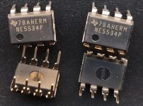
I know but still they are 5534. The only source I have for 5534A is RS & there the price is $1.2 ea.
I think PM took liberties with their graph. I’d put the 1/f at between 200 and 300 Hz.I just love these two graphs from the Precision Monolithics OP-27 datasheet
_
Place a ruler along the flat side of the rising 1/f curve and note where it intersects the horizontal x axis. That is the 1/f corner surely?
Alternatively I suppose you could say the corner is where the LF noise lies x dB above the thermal noise floor which is I suspect what PM did.
The 1/f corner is where the noise is 3dB above the noise floor. 1/f slope is as its name implies 1/f (10dB/decade) you need to fit that asymptotically to the extrapolated part of the curve to the left and then see the intercept with the extrapolated white noise floor (3nV/√Hz for OP27). Noise voltages don't add linearly for different noise sources, the powers add linearly. So 3nV/√Hz white noise plus 3nV/√Hz 1/f noise add to 4.24nV/√Hz at the corner. At 1/2 the corner frequency the 1/f noise is √2 times larger, ie 4.24nV/√Hz and adds with the white noise floor to give 5.2nV/√Hz.
The graphs in the datasheet follow this well.
The graphs in the datasheet follow this well.
Answer: NO. But you have used NE5532P. Use the better A grade types NE5532A.I have a amp and preamp from 1990 that uses more than a few TI 5532p and TL072, should I replaces those with newer 5532 ?
not much choice for the
TL072CP
TL052 is the tighter spec'd version of the 072 and should be equal or better. IIRC it is no worse in even a single spec.
Here is the list so far
Originals
5532 better is the TI SA5532AP
TL072CP ----TL052 or the new version TL072H
I need
LM833N
LM393N
Originals
5532 better is the TI SA5532AP
TL072CP ----TL052 or the new version TL072H
I need
LM833N
LM393N
- Home
- Source & Line
- Analog Line Level
- NE5534A end of life announced