Great work Oleg with the preamp too what are your PCBs ?
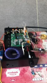
Also I have a NAC42.5 board in small design
With relay selector
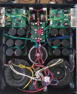
This is my design of board
I make this custom 42.5 board for this project
Attachments
Last edited:

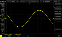
I (again) fried my amp, please help with advice! When I switched off the source at full volume (how stupid), it made an extremely loud pop, the DC protection kicked in, and since the amp sounds distorted. I checked rail voltages, they seem fine, also DC offset at the output hasn't changed. The output wave looks clean if nothing is connected, but into an 8 Ohm load it oscillates around 9MHz at the peak of the positive side with a 0.2V iput of 1kHz. Attached scope shots at the input and output of the positive power transistor and a zoomed in crop of the oscillating section:
Attachments
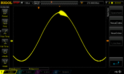
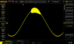

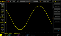
The amp looks fine, no smoked parts etc., and it measured fine before yesterday (see my older post with scope shots of stability). I hooked up my scope again and looked at the input of the driver transistor, see attached scope shot (1kHz sine with 0.2V). It seems there is no oscillation before the driver. Also oscillation is less at the output of the driver than at the output of the power transistor (see #465). What does that mean? Is there hope that only driver and power transistors are damaged and the rest is fine?
Attachments
This problem in both channels or only one ?
I watching the same oscillograph Picts when I tested the old Russian transistors in TO-3 case KT819G in 2009 year
Try connecting for testing the toshiba 5200
And let’s start again testing
Also Many old Soviet Union TO-3 transistors have a metallic sound some like speaker when I put more power sinus signal from generator
I think his inside n-p-n Cristal have a more free mechanical movement and song.. with signal
I think you are little burned the output transistor in power plus area. Also I not find the protection circuits in yours DIY boards and this design have a more chances to burn 🙂
Last edited:
Yes, they are from Halfin, the official Comset distributor, they still have them in stock. They sound sweeeeet. Both these new and my vintage BDY58s (in the original Naim boards) make sound from their TO3 cases if I play sinus with strong volume.
I have DC protection boards between amps and speakers, and also soft start power on boards, so I hoped there is enough protection.
Both channels show the same oscillation, but before the "crash" they worked perfectly stable. Should I just replace driver and output transistor and check if oscillation disappears?

Yes i told you about this
Some old TO3 can little burn and you have oscillograph pictures with distortion
You can opened the damage TO3 and watch on crystal
I think his will be have degraded structure
Some old TO3 can little burn and you have oscillograph pictures with distortion
You can opened the damage TO3 and watch on crystal
I think his will be have degraded structure

Good day
Good work Dear
but not full same with original
You build this board with parts in chassis ?
Last edited:

NAP140 clone works fine! I have a question output offset voltage. When turn on the amp. Offset is larger than 50mv. decreasing very fast and after perhaps half an hour after it decrease to 1mv and stay at 1 mv. How this mechanism work?
If there is no simple answer. Forget it 🙂
If there is no simple answer. Forget it 🙂
Last edited:
Define "simple answer" <wry smile>
Simply put, the components in the circuit change their electrical characteristics with temperature, which takes several minutes to settle down after power on. Since the offset is usually adjusted to be minimal beyond several minutes after power on, the initial offset is necessarily out of adjustment. The offset will also drift when the amplifier does a lot of work and gets hot and drift with changes in room temperature, say through the seasons.
Simply put, the components in the circuit change their electrical characteristics with temperature, which takes several minutes to settle down after power on. Since the offset is usually adjusted to be minimal beyond several minutes after power on, the initial offset is necessarily out of adjustment. The offset will also drift when the amplifier does a lot of work and gets hot and drift with changes in room temperature, say through the seasons.
BTW, 1mV dc offset is something to be proud of. Anything below 50mV is fine. Probably anything below 1V is tolerable in terms of speaker harm but I would say above 100mV for a NFB circuit (or servo controlled circuit) indicates a circuit fault or a design shortfall.
In terms of sound quality, a dc offset, directly driving a speaker, sets up an imbalance in currents in a push-pull output stage and this will affect the distortion of the amplifier, which you may be able to hear.
In terms of sound quality, a dc offset, directly driving a speaker, sets up an imbalance in currents in a push-pull output stage and this will affect the distortion of the amplifier, which you may be able to hear.
Thanks for your answers !
Simple answer may be "system behaves like a reactance". So, why its take that much time to stabilize?
1ma dc offset is related with Tr2's Hfe (in my system). I have many BC239C transistors. and I choiced the exact value for Hfe. I think it may change with changing diodes with led. Or changing source resistor (560 ohm or on some diagrams 620ohm). I choiced Hfe.
- Home
- Amplifiers
- Solid State
- NAP250 clone