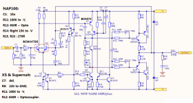
I don't know what subtlety is, lol. C7 is there to stabilize the bias circuit as you know but Naim puts it between C & E.I was trying to be subtle but it seems I failed. Anyway, what's your take on the purpose of C7 there?
I simply don't think well as I nearly freeze here but I have assumed C7 is just an oversized signal bypass cap. applied along the lines of Self's model blameless design. Often it's a smaller film cap. but nothing surprises me for JV's designs. This isn't his baby, it's 250.2 though. Perhaps someone with access to Steve Sells' previous work at Roksan and elsewhere has a hint of where this comes from, if not a error by the reverse engineer, who could be D. Albert or @Leo, not a Chinese reverse engineer, since hifidiy.net usually just watermarks and posts other people's work from the net .
Last edited:
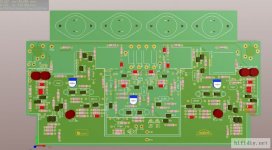
Good day Dear JPK this is NAP250.2 schematics of China nap250.2 clone supplier add this schematics with boards in attachment photos (with mistakes in roads hhhhhh).If you can make a working DR schematic please post here, or at least PM me :круто:
Attached new NAP250 schematics, reverse engineered by a member of a chinese forum:
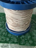
Buy this and you need wire …. Wire? Why wire? Aaaaaa …how to much ??? Wireeee… 🙂)))
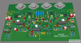
Also I think this first amp by Steve Sels design 🙂)) (many many many current sources …) after that new Naim designers make 250DR amp…
Attachments

Last edited:
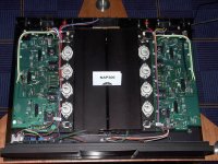
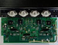
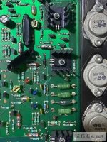
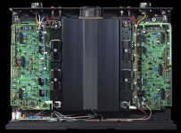
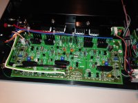
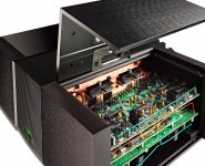
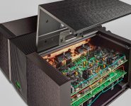
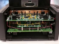
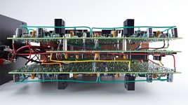
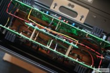
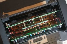
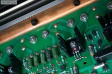
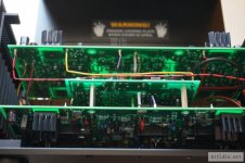
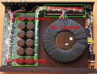
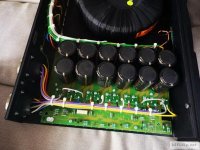
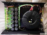
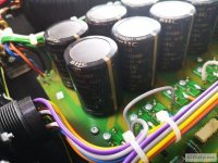
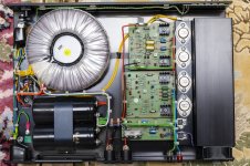
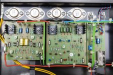
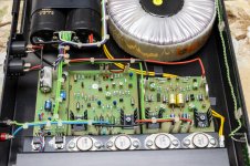
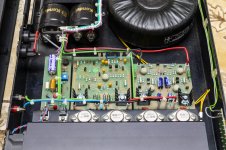
I attach some NAP300 DR and non-DR pictures, maybe it helps as well:
Attachments
-
 NAP300.jpg253.9 KB · Views: 260
 -
 NAP300 board.jpg115.7 KB · Views: 268
 -
 NAP300_detail_01.jpg56 KB · Views: 258
 -
 NAP300_detail_03.jpg42.8 KB · Views: 239
 -
 NAP300_detail_02.jpg51.8 KB · Views: 250
 -
 NAP300DR.jpg580 KB · Views: 255
 -
 NAP300DR_detail_01.jpg452.6 KB · Views: 243
 -
 NAP300DR_detail_02.jpg286.4 KB · Views: 237
 -
 NAP300DR_detail_03.jpg366.4 KB · Views: 240
 -
 reverse engeneered 2.jpg68.4 KB · Views: 268
 -
 reverse engeneered 1.jpg75.8 KB · Views: 268
NAP500 (I would love to see a non-DR schematic):
Attachments
-
 NAP500DR.jpg185.2 KB · Views: 203
 -
 NAP500_photo_01.jpg534.4 KB · Views: 198
 -
 NAP500_photo_01_crop.jpg284.4 KB · Views: 180
 -
 NAP500_photo_01_processed.jpg820 KB · Views: 165
 -
 NAP500_photo_02.jpg113.1 KB · Views: 181
 -
 NAP500_photo_03.jpg72.7 KB · Views: 181
 -
 NAP500_photo_04.jpg169.9 KB · Views: 185
 -
 NAP500_photo_05.jpg153.4 KB · Views: 200
 -
 NAP500_photo_07.JPG90.3 KB · Views: 203
 -
 NAP500_photo_06.jpg116 KB · Views: 200
 -
 NAP500_photo_08.JPG29.4 KB · Views: 180
 -
 NAP500_photo_09.jpg131.6 KB · Views: 175
 -
 NAP500_photo_10.jpg77.7 KB · Views: 168
 -
 NAP500_photo_11.jpg84.4 KB · Views: 160
 -
 NAP500_photo_12.jpg72.8 KB · Views: 159
 -
 NAP500_photo_13.jpg98 KB · Views: 153
 -
 NAP500_photo_14.jpg90.2 KB · Views: 157
 -
 NAP500_photo_15.jpg105.4 KB · Views: 161
 -
 NAP500_photo_16.jpg102.7 KB · Views: 167
 -
 NAP500_photo_17.jpg87.6 KB · Views: 185
more:
Attachments
-
 NAP500_photo_18.jpg98.4 KB · Views: 156
 -
 NAP500_photo_19.jpg77.6 KB · Views: 131
 -
 NAP500_photo_20.jpg74.1 KB · Views: 118
 -
 NAP500_photo_21.jpg73.3 KB · Views: 119
 -
 NAP500_photo_22.jpg74.4 KB · Views: 123
 -
 NAP500_photo_23.jpg76.1 KB · Views: 122
 -
 NAP500_photo_24.jpg81.1 KB · Views: 131
 -
 NAP500_photo_25.jpg148.2 KB · Views: 127
 -
 NAP500_photo_26.jpg90.5 KB · Views: 133
 -
 NAP500_photo_27.jpg45.5 KB · Views: 127
 -
 NAP500_photo_28.jpg101.4 KB · Views: 129
 -
 NAP500_photo_29.jpg127.4 KB · Views: 121
 -
 NAP500_photo_30.jpg101.4 KB · Views: 132
 -
 NAP500_photo_31.jpg108.7 KB · Views: 137
 -
 PS500_photo_01.jpg127.2 KB · Views: 140
 -
 PS500_photo_02.jpg94.2 KB · Views: 155
 -
 PS500_photo_03.jpg110.5 KB · Views: 144
 -
 PS500_photo_04.jpg78.8 KB · Views: 147
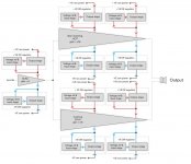
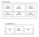
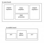
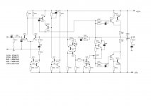
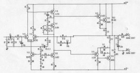
A NAP250DR diagram, taken from some Naim whitepaper, and 2 diagrams about the NAP500 (totally guess work): I am not sure about the PDIP8 in the middle, maybe it's a phase splitter, or some protection circuit...?
Attachments

Last edited:
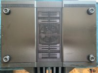
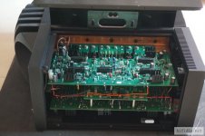
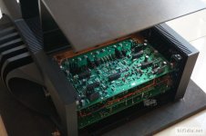
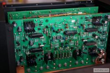
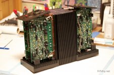
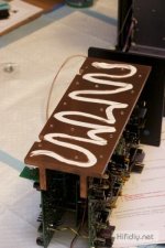
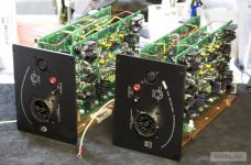
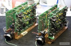
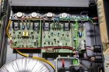
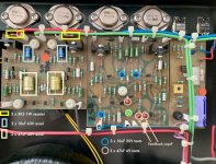
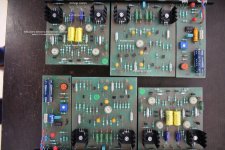
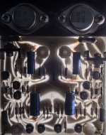
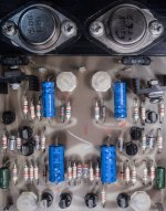
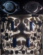
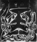
Some NAP135 pictures:
Attachments
-
 01.jpg428.9 KB · Views: 190
 -
 02.jpg479 KB · Views: 193
 -
 03.jpg565.4 KB · Views: 200
 -
 04.jpg549.1 KB · Views: 216
 -
 05.jpg572.6 KB · Views: 177
 -
 06.jpg560.7 KB · Views: 191
 -
 07.jpg492.7 KB · Views: 175
 -
 08.jpg530.6 KB · Views: 164
 -
 09.jpg649.4 KB · Views: 170
 -
 10.jpg509 KB · Views: 160
 -
 11.jpg847.2 KB · Views: 165
 -
 recap.jpg806.8 KB · Views: 168
 -
 service kit.jpg52.4 KB · Views: 176
 -
 service kit instructions.jpg276.7 KB · Views: 181
 -
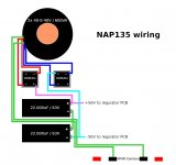 wiring.jpg85.3 KB · Views: 183
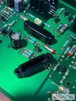
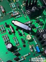
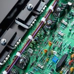
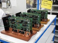
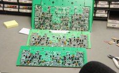
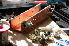
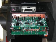
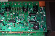
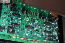
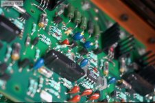
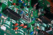
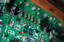
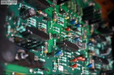
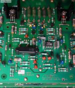
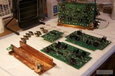
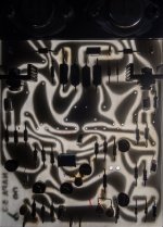
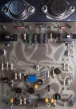
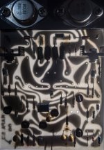
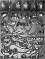
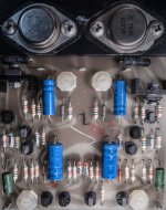
Finally, just in case, probably not needed, but PCB pictures of original NAP250 boards:
Attachments
-
 NAP250_PCB_NAPA_01.jpg466.9 KB · Views: 188
 -
 NAP250_PCB_NAPA_02.jpg431 KB · Views: 196
 -
 NAP250_PCB_NAPA_03.jpg455.1 KB · Views: 180
 -
 NAP250_PCB_NAPA_04.jpg412.1 KB · Views: 183
 -
 NAP250_PCB_NAPA_05.jpg460.7 KB · Views: 172
 -
 NAP250_PCB_NAPA_06.jpg566.2 KB · Views: 189
 -
 NAP250_PCB_NAPS_07.jpg481.3 KB · Views: 189
 -
 NAP250_PCB_NAPS_08.jpg516.8 KB · Views: 184
 -
 NAP250_PCB_NAPS_09.jpg604.7 KB · Views: 166
 -
 NAP250_PCB_NAPS_10.jpg488.5 KB · Views: 162
 -
 NAP250_PCB_NAPS_11.jpg590.9 KB · Views: 166
 -
 NAP250_PCB_NAPS_12.jpg615.7 KB · Views: 183
Nice work Jpk73!!! Thanks!!!Finally, just in case, probably not needed, but PCB pictures of original NAP250 boards:
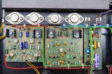
The NAP300 photo also shows C7 in a different place, as does the Nait5i.I simply don't think well as I nearly freeze here but I have assumed C7 is just an oversized signal bypass cap. applied along the lines of Self's model blameless design. Often it's a smaller film cap. but nothing surprises me for JV's designs. This isn't his baby, it's 250.2 though. Perhaps someone with access to Steve Sells' previous work at Roksan and elsewhere has a hint of where this comes from, if not a error by the reverse engineer, who could be D. Albert or @Leo, not a Chinese reverse engineer, since hifidiy.net usually just watermarks and posts other people's work from the net .
I didn’t know Sells worked at Roksan.
As we have commented in the past, Sells appears to have lost/discarded the original recipe. Not good.
Hence I am most interested in a non-DR NAP500. It seems to me the 500 has 250/300-like main boards with the added circuit around the PDIP8 in the center, plus the smaller middle PCBs, plus a fan like the 135. So are we able to put together a NAP500 clone...?
Last edited:
The 500 has two amps in bridge mode, each with a regulator, per channel. 16 power transistors in total. Perhaps like a bridged 135.
I've been poring over the XS2 schematic posted earlier (thanks indeed, jpk, you've shed light where there was darkness!) and that really surprised me. l've seen a few unusual topologies but that one has me stumped. Is it a "clever clogs" tech idea that didn't really sing or dance or is it a cinderella waiting for someone to slap on the makeup and hairdo, teach a few moves and presto! A star performer is (re)born?
As it stands, I understand XS is not exactly a popular line but what does that matter to Naim fans? They'll enthuse and slaver over the brand name regardless of what's inside or should that be "not inside"
As it stands, I understand XS is not exactly a popular line but what does that matter to Naim fans? They'll enthuse and slaver over the brand name regardless of what's inside or should that be "not inside"
Yes dear Steve permit only “Steve design” in all Naim amps but old design it’s Julian Vereker ideas and music soulThe NAP300 photo also shows C7 in a different place, as does the Nait5i.
I didn’t know Sells worked at Roksan.
As we have commented in the past, Sells appears to have lost/discarded the original recipe. Not good.
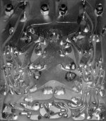
please see photos of old board nap 250 published by jpk73 and you watch soul design 🙂
If I working in Naim Audio I will changed of all new Naim amps And change all design of all amps and preamps boards … but I go to another way with my teacher Julian Wereker 🙂
Very interesting somebody in Naim Audio designers read this forum or not ? Hhhhhh 🙂))
Last edited:

I own a Supernait v1, I guess it is practically an XS with a larger PSU plus a DAC and preamp and rec-out etc., but it sounds typical Naim and very good indeed (I prefer the Supernait to the Avondale NCC300 BTW). I owned NAP90, NAP135 (both passive and 6* active into NBLs), NAP500 in the past and can tell that the 500 is a totally different beast (it outperformend the active setup by far). Stupid me that I didn't open it and took pics before I had to sell it, but at that time I wasn't into diy yet...
Last edited:
I am not so sure if it's just a bridged 135. There might be more into it...The 500 has two amps in bridge mode, each with a regulator, per channel. 16 power transistors in total. Perhaps like a bridged 135.
- Home
- Amplifiers
- Solid State
- NAP250 clone