Looking for a little advice. I built a couple boards with spare parts I scrounged together, and used the stock schematic with the protection circuit intact. One functions perfect, the other has no gain. Both bias fine and have very low DC on the outputs but one just doesn't make gain in the VAS. All DC voltages are the same on both boards, the AC is the same in the LTP, and differs when it gets to the VAS where one simply fails. I thought it was a malfunctioning protection circuit that was dumping the voltage but i removed the two protection transistors and the problem remained. Should i replace the ZTX's? even though the DC matching implies they are functioning? Any guru have some advice?
The gain is determined by the feedback divider network. If the section splitting off from the 27k feedback resistor where it connects to the inverting input transistor of the long tail pair - that is the arm with the 1k resistor and 68uF in series - does not connect to earth properly then you will have a closed loop gain of one. Check the soldering joins in this area and that the 68uF capacitor - perhaps one of the scrounged parts - is not defunct.
Take a look at an overview and estimated specifications of original NAP 250 and other early Naim models here: Modifying Naim Audio power amplifiers You might notice that the real NAP250 is a tank - a monster fitted with quite a large and expensive 450VA toroidal transformer that has a much higher current rating to overcome its regulation losses (i.e. voltage sag) and linear regulator losses.For building Nap 250 clone, what is the recommended transformer and capacitance ratings?
35v 500A toroid and 30,000uf is enough?
Thanks
The Chinese clone kits all have their designs based on the original NAP250 amplifier schematic but up until recently, the kits were were called after the NAP140 model, because it was popular and had a cheaper, smaller and unregulated power supply but limited power output.
It is difficult to buy a transformer with the specified 28VAC windings but a standard 30VAC rating is excessive for some of the essential transistor types used and 25VAC is not really enough. So, I had several transformers wound for the purpose and sold those I didn't need for my cost. These were nominally 200VA rated but I decided to build my next amp. in a "dual mono" arrangement and used 2x120VA transformers which proved to be rather good sounding.
The main PSU electrolytics are Now Rubycon types but there is nothing wrong with Kendiel or other Main electrolytic Capacitors of 4,700-10,000uF in a 50-63V voltage rating, depending on your actual rail voltages. Don't overdo the capacitance. Enough is enough 😉
The gain is determined by the feedback divider network. If the section splitting off from the 27k feedback resistor where it connects to the inverting input transistor of the long tail pair - that is the arm with the 1k resistor and 68uF in series - does not connect to earth properly then you will have a closed loop gain of one. Check the soldering joins in this area and that the 68uF capacitor - perhaps one of the scrounged parts - is not defunct.
Dude, thank you for the help. It turned out to be a 100K resistor where 1K belonged. Considering alcohol was the project's catalyst, it all makes sense now.
Take a look at an overview and estimated specifications of original NAP 250 and other early Naim models here: Modifying Naim Audio power amplifiers You might notice that the real NAP250 is a tank - a monster fitted with quite a large and expensive 450VA toroidal transformer that has a much higher current rating to overcome its regulation losses (i.e. voltage sag) and linear regulator losses.
The Chinese clone kits all have their designs based on the original NAP250 amplifier schematic but up until recently, the kits were were called after the NAP140 model, because it was popular and had a cheaper, smaller and unregulated power supply but limited power output.
It is difficult to buy a transformer with the specified 28VAC windings but a standard 30VAC rating is excessive for some of the essential transistor types used and 25VAC is not really enough. So, I had several transformers wound for the purpose and sold those I didn't need for my cost. These were nominally 200VA rated but I decided to build my next amp. in a "dual mono" arrangement and used 2x120VA transformers which proved to be rather good sounding.
The main PSU electrolytics are Now Rubycon types but there is nothing wrong with Kendiel or other Main electrolytic Capacitors of 4,700-10,000uF in a 50-63V voltage rating, depending on your actual rail voltages. Don't overdo the capacitance. Enough is enough 😉
Thank you for the answer and explanation, appreciate it.
Preamplificator changes the all colour of Nap250. Please write your source.
Result of Nac42.5 or NJM4580 are different. Or without preamp. I use Fiio (hi-res player) as a source.
Result of Nac42.5 or NJM4580 are different. Or without preamp. I use Fiio (hi-res player) as a source.
Which post do you refer to and do you mean original Naim or Chinese cloned designs? All Naim designed preamps from that early period to now, will sound a little different, whether they are powered with SNAPS supplies and connected to a Naim or any other brand of amplifier. The clones are variable and those I've listened to aren't comparable to the original, nor would you say they are particularly good.
For interest, the appropriate preamp for the first "chrome bumper" NAP250 version in 1975, was NAC32. Since then (this is a $$$$ price region) upgraded versions have followed the amplifiers. I believe NAC32.5 still suits NAP250DR and NAC282 complements the newest DRMK2 model).
For interest, the appropriate preamp for the first "chrome bumper" NAP250 version in 1975, was NAC32. Since then (this is a $$$$ price region) upgraded versions have followed the amplifiers. I believe NAC32.5 still suits NAP250DR and NAC282 complements the newest DRMK2 model).
I had connected my hi-res player to clone nap250 (or LJM l12-2), I was listening music without any preamp. When I use an preamp, sound changed a lot (better way). I want to say that if someone comment about an amp.'s sound, he has to say what he used for input device&preamp.Which post do you refer to and do you mean original Naim or Chinese cloned designs? All Naim designed preamps from that early period to now, will sound a little different, whether they are powered with SNAPS supplies and connected to a Naim or any other brand of amplifier. The clones are variable and those I've listened to aren't comparable to the original, nor would you say they are particularly good.
For interest, the appropriate preamp for the first "chrome bumper" NAP250 version in 1975, was NAC32. Since then (this is a $$$$ price region) upgraded versions have followed the amplifiers. I believe NAC32.5 still suits NAP250DR and NAC282 complements the newest DRMK2 model).
Yes of course you can do this it will even give you power factor correction For the the last 20 years or so I have been involved with UPS units varying from a few hundred watts to a a few megawatts ! This being said the UPS technology is far more difficult/costly to implement than a transformer /rectifier and a few caps
Trev
Another thing you can do is to trade a little efficiency for a longer charging time. The issue with a simple rectifier-capacitor is that if the capacitance is small the transformer recharging window is longer (good) but the voltage ripple is higher (bad). By using bigger capacitance, the ripple decreases but the recharging window shortens and the peak transformer current gets bigger.
Why does peak transformer current matter in a audio amplifier? Aside from requiring beefier rectifier diodes, high peak currents can saturate the transformer core. This matters because the point of the laminated, iron core is to conduct the magnetic flux by providing a very low reluctance path (compared to air). But the core can saturate causing any further flux to escape the core and spread well outside of it and all over your amplifier.
Other than using a switch mode psu approach, which is complicated and electrically noisy, you can simple make a two-stage analogue supply. Imagine a first supply that generates, say, 50V. Have this feed an analogue regulator that lowers the voltage to, say, 40V and charges a second capacitor. By this means, some efficiency can be traded for a much longer transformer recharging window and reduced peak current.
Last edited:
I was looking the high-res orj. nap250 pictures on the web. I can say that R18&R19 are all the same with schematic(390&680ohm). But, for R14&R15 I couldn't find any picture showing them 680&560 ohm . Three of them R14&R18 was 470&150(180?) ohm. I'm not sure about the values but, there not the values as in the schematic. Are you sure about R14&R15? Did you see that values on the orjinal Naim circuits? Or this values are changing in the Naim Amp.?

Last edited:
This is the schematic that I believe shows them as 680 & 560:
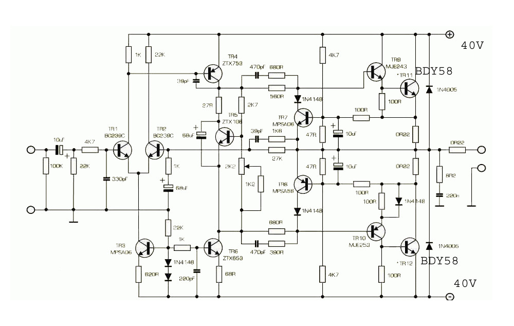
But yeah, this board has 470 & 150:
as do several other boards I've seen pictured.
Which is right? I haven't a clue... but 680/560 sims better in SPICE.
But yeah, this board has 470 & 150:
as do several other boards I've seen pictured.
Which is right? I haven't a clue... but 680/560 sims better in SPICE.
Attachments

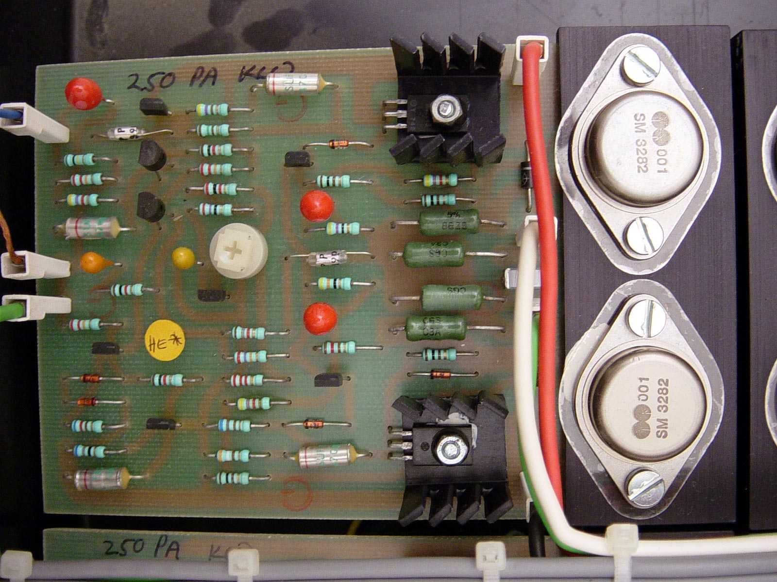
There are problems in using internet images without proper references to what they are. I could assume that the above pics are of a Naim factory or service centre modified NAP 250 (note the proprietary NA001 power transistors on an earlier PCB) though the assembly looks odd (thermal grease seems to be insufficient). It also has Zetex E-line transistors everywhere except the input pair and the output stage transistors, so what is it or what has it really become?
Even if modifications are factory approved, it still means you can't rely on the original schematic as a reference. In reading JV's last interview, you get some idea of what was on his mind when he decided to add those networks to the flagship 250 design. Here's the extract:
I also wondered why JV was so desperately trying to get his already established design to "work". Well, linear regulation does sever the direct link to the power source and that opens yet another can of worms about where the original "Naim sound" or that of any other similar topolgy amp. comes from 😕
Even if modifications are factory approved, it still means you can't rely on the original schematic as a reference. In reading JV's last interview, you get some idea of what was on his mind when he decided to add those networks to the flagship 250 design. Here's the extract:
"Back when I was trying desperately to get the NAP200/250 to work, I remember someone showing me a modular American amplifier - Spectrasonics, I think it was called. I looked at the circuit and noticed a couple of resistors and capacitors which seemed to be different from anything I'd seen in other designs. This got me thinking, and then I realised that of course the positive half of the amplifier and the negative half of the amplifier are bound to be different, but they share a common feedback loop, so you have to get the two halves accurate in terms of phase gain, or you'll never make the design stable - and there were these little phase-correcting networks doing just that....
I also wondered why JV was so desperately trying to get his already established design to "work". Well, linear regulation does sever the direct link to the power source and that opens yet another can of worms about where the original "Naim sound" or that of any other similar topolgy amp. comes from 😕
Orjinal NAP250 picture
Ok! But, I couldn't find any picture of our schematic on the web. Can anybody send us an orjinal NAP250 picture? I want to try orjinal values, not the schematic from Just one thing about music - when it hits you feel no pain.
From Naim's forum, there are NAD140 pictures with double digit resistor values like 33ohms.
I'm trying 150&470 ohms. I feel like it's better & more transparent. Or not! Up to now everything are ok 🙂
The schematic posted and seen everywhere, is that of the original issue, "chrome bumper" style NAP 250 (power amplifier board only - not including its similar sized, dual regulator board. If you remove the regulators, you have quite a different amplifier, whatever other changes you make. The images shown in the old Pinkfishmedia article I linked to, are also the original products or stated otherwise. They only show earlier revisions and the pics are probably too small to identify resistor codes. When I check larger, high resolutiom images on the net, they are seldom original products anyway and many have also been modified with some expensive and rare substitute components.
Otherwise, there have also been manufacturing changes from one edition of the amplifier models to the next. That is inevitable when semis are upgraded, as they have been many times for NAP250. It's also typical of any electronic product that has been around 45 years, that is should be amended to suit replacement semis anyway. In this case, the changes to the output transistors at least, were dramatic and probably meant making more changes to restore sound quality.
As you say, that image above, is of NAP140 and just to clarify, it's a newer revision and isn't quite the same design as NAP 250 anyway, since it uses unregulated power, lower supply voltages and that means changes to biasing resistors, feedback, thermal compensation and other minor changes to ensure consistent operating conditions. I would not use it as a reference for NAP250.
What about NAP140? Schmatics looks like similar to NAP250. It must be different? Is that values (470/150) for NAP140?

This is the schematic that I believe shows them as 680 & 560:
But yeah, this board has 470 & 150:
as do several other boards I've seen pictured.
Which is right? I haven't a clue... but 680/560 sims better in SPICE.
I have a 1980's brochure showing the internals of the Olive series NAP250 which shows values of 470R and 150R that you mention.
Re your simulations with 680/560, I don't see where you simulated amplifier with the regulated power supply connected.
It took JV a lot of trial and error testing to make the NAP160 into the NAP250 to make these elements compatible.
One could easily imagine possible flow on effects with changing just one value of resistor or capacitor anywhere in the power module or the regulator module being a root cause.
If the supply rails of an amplifier are increased then this will affect any common emitter stages in the system such as the VAS and both LTP transistors.
Under dynamic conditions the current drawn through collector loads will change the voltage seen at the collector of any common emitter stage.
This will change the collector to base capacitance in these stages whereas such has an inverse relationship with the square root of such applied voltage.
There is need to consider the differences between a system with in voltage rails in excess of 50 volts with an original design calling for 40 volt rails as per the original design. This is a big leap.
Last edited:

Exactly, though for the record, at least the early versions of NAP 140 have power rails of only about 34V. If nothing else, NAP250's regulation by itself makes a difference to the dynamic range you can hear.
@mdardeniz, I haven't found such a clear print of the NAP140 schematic as you posted above in #216. Could you post the complete one here or if Jeff would prefer it, in the NAP 140 thread, so that we can all be clear about what is being discussed or compared? Readers of Naim amplifier threads have been groping in the dark here for many years so it would be good for all to be comparing the correct designs rather than variable kit clones of something different.
@mdardeniz, I haven't found such a clear print of the NAP140 schematic as you posted above in #216. Could you post the complete one here or if Jeff would prefer it, in the NAP 140 thread, so that we can all be clear about what is being discussed or compared? Readers of Naim amplifier threads have been groping in the dark here for many years so it would be good for all to be comparing the correct designs rather than variable kit clones of something different.
Last edited:
Aha! thanks mdardeniz for the images posted at #4307/8 in the NAP140 thread. They show what was likely copied directly, as in reverse-engineered from a real, later series NAP 140. I now have a little more trust in the designs published by HifiDIY, as long as they are identified correctly.
- Home
- Amplifiers
- Solid State
- NAP250 clone