Hi...
I think you mean me ? Dont know were i have found the 15 Ohm. Somewhere in the I-Net.
I have canged the value to 10 ohms now. I will complete the board and give the amp a try....takes time...to many other projects i have to finish....
I dont know much about electronic...everything i know i learned by my self...in many cases perhaps not enough...but i have fun. I find a correct schematic i can make a pcb... 🙂
In this case, as i wrote....to many plans of a nap clone in the i-net...
Greets
Peter
Avondale Zobel is 8R2
Also Avondale change the original schematic and parts.
Better way buy in eBay the original boards of power amp
You have the original design and original parts
Also Avondale change the original schematic and parts.
Better way buy in eBay the original boards of power amp
You have the original design and original parts
Last edited:
I have taken a short look to the schematic. It seems very similar to the Nap schematic. Only little differences at some values by a first look. I think i copy the schematic and make a comparison to my schematic. We will see.....
Hi....
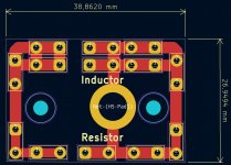
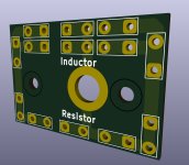
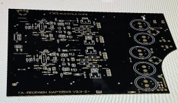
i made a little pcb for outfilters. Inductors with 15mm diameter, different length will fit, resistors with 10 watt. If there is space enough it can be mounted on the + bindingpost. The holes have 1,3 mm diameter because i used 6,3 mm faston print connectors. For input/output it is also possible to solder the print connectors in. How practical i will see. I think i order pcb's.
In the past i always used experimentel pcb's.
Greets
Peter
Attachments
If i compare the NCC schematic with the Nap schematic there are more components on the Nap board. The path MPSA06/MPSA56 ist missing on the NCC. Resistor values are different in the voltage rails. ZTX753 has an emitter resistor, liittle changes on resistor values (orginial ?) and so on....
It reminds me of the mods shown on http://www.acoustica.org.uk/t/naim/power_amps.html
Dont know which amp is better. I think the Nap schamatic is the older one ?
Greets
Peter
It reminds me of the mods shown on http://www.acoustica.org.uk/t/naim/power_amps.html
Dont know which amp is better. I think the Nap schamatic is the older one ?
Greets
Peter
NCC200 Sounds better, they left out the protection.
Also we can say that is no longer the typical Naim sound.
Some people only want the original Naim sound!
I also have a schematic modified by Greg Ball, take a look at that.
I did tested the Naim with my own PCb (HOME BREW) many times.
I started with 2 different eBay kit but ended something similar to the NCC200. (sounds better to me)
In the near future I may test the one was moded by Greg.
Right now busy with other projects.
Attachments

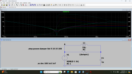
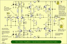
From "Audio Power Amplifier
Design Handbook" by Douglas Self MA, MSc. Page 202. Effect of output inducters damping resistor dependency. I think damping resister value can be found only with testing.


Design Handbook" by Douglas Self MA, MSc. Page 202. Effect of output inducters damping resistor dependency. I think damping resister value can be found only with testing.
Thanks for the information Gabor, which amp sounds better. As i wrote....give me a schematic and i make a pcb 🙂
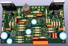
Not finished yet. It is the first try. But its crossing free...
I have to change a few values to correspond the plan of Greg Ball. But that is easy to do. Perhaps i have to change pinouts of transistors....
I the moment the input with its capaticitor dosn't satisfy me...
I will see what can i do....
Greets
Peter
Attachments
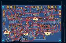
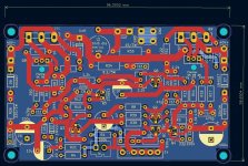
Found a little mistake. The emitter resistors at Q1, Q2, R38/R39 had the wrong value, corrected...
Hi....
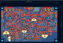
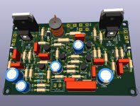
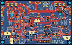
It took hours...now i think i can live with this NCC pcb, i have made. I have done a few changes.....feedback resistors close to the output, transistors moved to other places. Controlled the pinout for the transistors MPSA 06, ZTX108 and so on...
The input has a signalgorund. If not needed i can short R4/10 ohm.
I hope all Mods of Mister Greg Ball now in....another look tomorrow.
Good night
Peter
Attachments

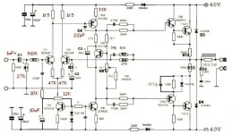
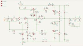
Where did you find this NCC schematic? I didn't see that much low value for C9 for example (Must be 39p or bigger & <100p). Or, what is the meaning of C14 ?
The plan https://www.diyaudio.com/community/threads/nap-140-clone-amp-kit-on-ebay.112453/page-48
It is easyer to read as the plan Gabor shows above. In the original NCC schematic are 47pf set for C9 (you are right).
You can ask me whats the meaning of C14. I dont know.
I can draw a schematic and make a PCB. My electronic knowledge is to small....sorry....
I only can hope Mister Greg Ball has done everything right in his NCC Mod...I tried to find more information about the mod, but the SKA forum is dead.
You can read about the NCC mod in the pinkfishmedia forum, but no schematic, no pictures.
C14 is mod for next baxandall network solution about 1980-1985yy
Better linearly with C14=22nf
Better linearly with C14=22nf
Attachments
Last edited:
Hi....
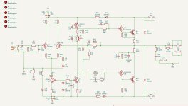
in the schematic i have marked the original values in blue ( shows what is different to the Greg Ball Mod). In the Mod schematic only R9/22k is deleted.
Because that is the only different, exept the values, i can built the original NCC or the Mod NCC. R9 is also marked on the pcb.
The Mod schematic, Gabor posted, is really small. I made a sreenshot of my KiCad schematic with the marked values. i hope every thing is right now....
I had to realize that one resistor at the ZTX753 was missing, corrected.....
Attachments

- Home
- Amplifiers
- Solid State
- NAP-140 Clone Amp Kit on eBay