Lol😀
I am tired of this debate, there is no action and i dont think any other topology will outperform this one.
I am tired of this debate, there is no action and i dont think any other topology will outperform this one.
it's true that it hasn't moved much for a long time, it's a bit like being on a treadmill that doesn't move forward.
sincerely, I would come and play with you, but I have so much work and so little free time 🙁
sincerely, I would come and play with you, but I have so much work and so little free time 🙁
Its never moved anywhere, maybe those who got it right left and those who are searching for something are still here.
But we sure know alot, and really alot... now.
😛
But we sure know alot, and really alot... now.
😛
all the same, there have been great advances in the understanding of what Julian Vereker wanted to do thanks to many competent contributors but the thing is that the fashion is fading.
People jump from model to model as they do in life.
few people are able to devote their time to just one thing until it borders on perfection, unless they are Japanese like the art of tea.
People jump from model to model as they do in life.
few people are able to devote their time to just one thing until it borders on perfection, unless they are Japanese like the art of tea.
its just a diyfun, 1 amplifier for everything and every music program out there.
Analog is a strange thing compared to computers, if it works and well, it stays forever😀
Analog is a strange thing compared to computers, if it works and well, it stays forever😀
Its a straight forward Quasi Complementary Design
The sound should be rather nice
There is a big following and fans of Quasi Amplifiers.
The transistors being used are basically still available.
Depends on the board layout.
The typical low noise transistors could be used for the input pair
And the ZTX653/753 tend to be straight forward and work well.
I have seen TIP type transistors being mentioned
which would not seem the ideal choice.
Its easier to use original MJE243/253 or possible even the common Fairchild 3503/1381
Whats great is any basic known performance NPN output device
like 5200 or 3281 could be used
And since its a hobby.
Some people really enjoy the using the very Durable TO3 packages or the M200
packages as used by NAIM
Unfortunately the Sanken M200 packages are a little hard to get now.
But have been curious how the NTE M200 packages perform.
Since they seem to be somewhat available ?
Has anybody tried or had fun with the NTE 92 ???
Attachments
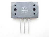
A glib and not too serious reply would be that NTE92/93 are probably re-badged fake versions of original Sanken 2SC2922/2SA1216. Nobody would set up from scratch to manufacture LAPTs with that unique and effectively obsolete package unless they were targeting us audiophools with something much cheaper.
At least NTE's datasheets appear to be honest and show that at 20 MHz Ft, these are intermediate between standard epitaxials (4MHz) and Sanken's 70MHz LAPTs. NTE92 Datasheet | NTE Electronics - Datasheetspdf.com. However there are other regular audio products from Toshiba that are better and quite cheap - TTC5200/TTA1943 or original 2SC5200N/2SA1943N or any of On Semi's range of 30 MHz Ft audio power transistors, for example. Then there are the superb Sanken TO3P LATPs that LJM uses in some of his designs such as L12-2. These will also be quite large enough for NAP140 clones, as long as you keep to the original spec. of ~ +/- 35VDC rails.
Finding Allegro Sanken distributors isn't easy but in North America, Digikey hold reasonable stock of current products and they despatch from global distribution houses, such as Singapore, for my region.
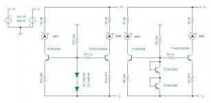
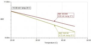
As far as the mentioned issue with Constant Current Source drift
If using a diode type CCS if you use all similar transistors, and also use same
transistors or complementary transistor wired as diodes.
Then the drift will not be as much from ambient temperature
Showing here I set AM1 and AM3 to be 11 mA at 22 C temp
then did basic temperature sweep from 20 to 35 C

Green line transistor used as diode shows less drift
Blue line diodes shows larger drift from temperature

for the amplifier in the thread you could simply use all ZTX transistors in the CCS
and also as diodes. and the CCS would be slightly more stable.
I dont see it really as issue, countless amps use basic diode type CCS without issue
I just found it a interesting exercise to be able to just use transistors as diodes
on the existing board if you really feel CCS drift changes the sonics of the amp at different temps.
If using a diode type CCS if you use all similar transistors, and also use same
transistors or complementary transistor wired as diodes.
Then the drift will not be as much from ambient temperature
Showing here I set AM1 and AM3 to be 11 mA at 22 C temp
then did basic temperature sweep from 20 to 35 C
Green line transistor used as diode shows less drift
Blue line diodes shows larger drift from temperature
for the amplifier in the thread you could simply use all ZTX transistors in the CCS
and also as diodes. and the CCS would be slightly more stable.
I dont see it really as issue, countless amps use basic diode type CCS without issue
I just found it a interesting exercise to be able to just use transistors as diodes
on the existing board if you really feel CCS drift changes the sonics of the amp at different temps.
Attachments
Because we tend to collect a lot of cheap TO92 transistors such as BC550 and maybe sort them for matches or noise level, could you test that or a similar small signal type in your TINA simulation, assuming it's still set up? I do expect it to be the same as your BJT - just curious though.
Last edited:
The transistor as a diode will usually reduce temp drift better
if all the transistors all match.
A lot of designers like to use T0-225 or T0-126 packages for a Vas
transistor, so they will tend to use the same package for the CCS.
When tested in models, It seems the larger package transistors,
used in a CCS will drift more. likely from larger surface area. So the same larger transistor is better to be used as a diode.
Seems smaller T092 are less likely to drift
So likely using all T092 in a CCS would remain pretty steady
Attachments
Guys,
Have you ever seen Matrix and Existenz movies ?
What we do in here reminds me these two movies mentioned.

The very first shots of a big star explains it. Listening to Hifi propably and falls a sleep cuz sound must be very pleasent, as soft as almost like somebody singing?.
All the three series brag about the one, source and cables, can also be applied to Hifi right ?
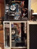
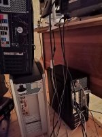
I mean, have you ever moved cables inside your computer for better acoustics ? It is one of the source problems, splash or tighten up the cables if something is bothering you in ur acoustic system. 3 computers has been bought last month with different sound cards, to make sure what i am talking about. Just to do this tests(change power supplys and move wires). Pics are below.
This guy here
 said it cannot be explained "the sonics" 😀, it can only be shown. Its the same with this topology
Next is the movie existenz, the special thing about it is that there is a technology present, a gamepad which reminds me that of a naim topology... lol.... i mean.... its the one everyone uses and its very sensitive😉 as almost as its alive if its working properly
It is the same with us in here, we have it from a year 1971 and most of us do not still accept it lol.....
Maybe one wants something different in terms of "acoustics and sound", using the same topology, different layout, caps and resistors will give us some other good combination of rhythm, sonics and acoustics overall.
Literally, we can hear PSU diodes with that topology, then how cant it be the one and the only ? what a chicken.. 🙂
This image crossed my mind today:
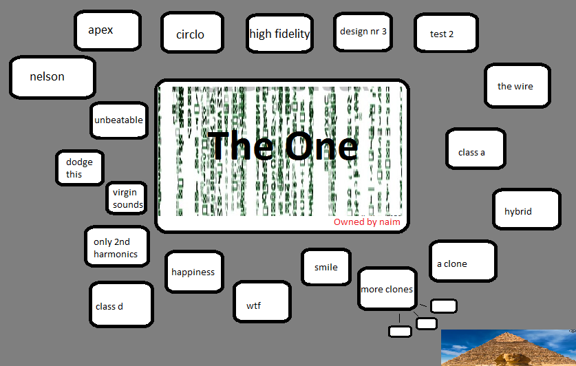
I am not trying to pull or push someones amplifier design up and down.... its more like what is wrong and what is right ? The Truth.
How can you beat the ONE ? How is this even possible ? 😀
This scheme runs nicely even on 5mA bias and 7-8mA vas, totalling ~15mA per channel, beats any class A out there. And its do-able for ~10$ per channel + case and a transformer cost.
Investing time in this design and more ppl will be by far more rewarding... we could standardize "hifi".
Another source problem is this:
Just moving connections back and forward between preamp(pc) and poweramp might fix acoustics and rhythm with it.
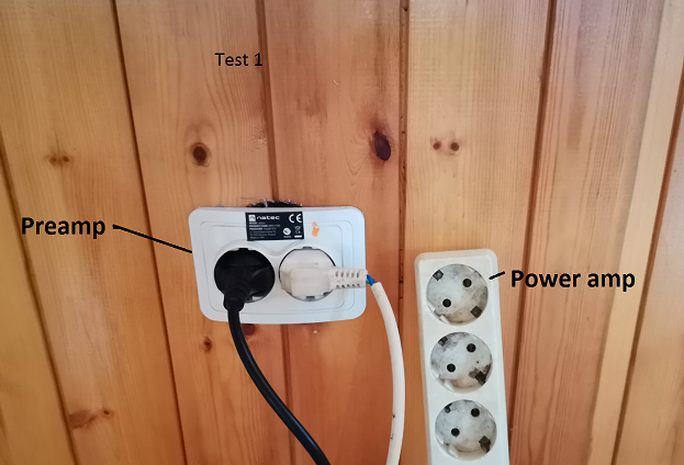
Why trying to fix/correct something that can be easly fixed at an earlier stage.
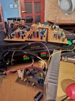
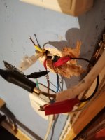
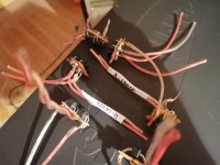
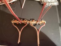
Now to the diodes. I used OFC copper for diode to capacitor and transformer connections. And have been manipulating with various distances from capacitors and transformer for best result. Getting them correctly means correcting impedance across amplifier powersupply lines. This is very important in this design... you can hear every VF drop of a diode in here!.
Latest build, 1 channel only cuz i have no PCB-s left, i kept this one hidden 🙂, no protection circuit is installed, didnt even bother installing tantalums, but they are prepared.
The first picture represent my respect for ppl in this forum🙂
In overall what a ..... we should study this carefully😛
Have you ever seen Matrix and Existenz movies ?
What we do in here reminds me these two movies mentioned.
The very first shots of a big star explains it. Listening to Hifi propably and falls a sleep cuz sound must be very pleasent, as soft as almost like somebody singing?.
All the three series brag about the one, source and cables, can also be applied to Hifi right ?
I mean, have you ever moved cables inside your computer for better acoustics ? It is one of the source problems, splash or tighten up the cables if something is bothering you in ur acoustic system. 3 computers has been bought last month with different sound cards, to make sure what i am talking about. Just to do this tests(change power supplys and move wires). Pics are below.
This guy here
Next is the movie existenz, the special thing about it is that there is a technology present, a gamepad which reminds me that of a naim topology... lol.... i mean.... its the one everyone uses and its very sensitive😉 as almost as its alive if its working properly
It is the same with us in here, we have it from a year 1971 and most of us do not still accept it lol.....
Maybe one wants something different in terms of "acoustics and sound", using the same topology, different layout, caps and resistors will give us some other good combination of rhythm, sonics and acoustics overall.
Literally, we can hear PSU diodes with that topology, then how cant it be the one and the only ? what a chicken.. 🙂
This image crossed my mind today:
I am not trying to pull or push someones amplifier design up and down.... its more like what is wrong and what is right ? The Truth.
How can you beat the ONE ? How is this even possible ? 😀
This scheme runs nicely even on 5mA bias and 7-8mA vas, totalling ~15mA per channel, beats any class A out there. And its do-able for ~10$ per channel + case and a transformer cost.
Investing time in this design and more ppl will be by far more rewarding... we could standardize "hifi".
Another source problem is this:
Just moving connections back and forward between preamp(pc) and poweramp might fix acoustics and rhythm with it.
Why trying to fix/correct something that can be easly fixed at an earlier stage.
Now to the diodes. I used OFC copper for diode to capacitor and transformer connections. And have been manipulating with various distances from capacitors and transformer for best result. Getting them correctly means correcting impedance across amplifier powersupply lines. This is very important in this design... you can hear every VF drop of a diode in here!.
Latest build, 1 channel only cuz i have no PCB-s left, i kept this one hidden 🙂, no protection circuit is installed, didnt even bother installing tantalums, but they are prepared.
The first picture represent my respect for ppl in this forum🙂
In overall what a ..... we should study this carefully😛
Attachments
My last tought on this topic is this:
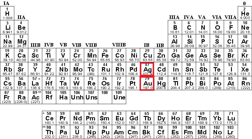
When i soldered input, feedback small signal and emitter connections of a power transistors with a silver containing tin, there was a huge difference in amplifiers sound quality, almost as i changed out the amplifier for another one.
I dont know, if my Toshiba's (to shiva's🙂) have gold "flash, plating or some oxide in it), but that could determine the perfomance of a naim amplifier.
Manipulating with materialism is the key and the actual END lol, alot more rewarding than developing new designs and simple clones.
Its not that easy to get best real HIFI out of this circuit, but its possible, sonics are just so incredible with this topology.
You understand that all solders have resistance about 10-15 times worse than copper?... All of them, no matter silver, or unobtenium alloy... And that silver in solder is not for conductivity, but mechanical joint strength?
I think the solder is the last thing to worry about or to try to listen to in DIY generally untested and unmeasured gear 🙂 Why don't we keep the voodoo to ourselves? I've been there, though, I know imagination is a powerful ally.
I think the solder is the last thing to worry about or to try to listen to in DIY generally untested and unmeasured gear 🙂 Why don't we keep the voodoo to ourselves? I've been there, though, I know imagination is a powerful ally.
Ur right, but 😀
If we take:
Pb 63/37% starts to melts ~190C
Pb free 99.9% starts to melt ~221C
Then we can conclude, that they also cool down @ different temperature rates.
I have 5 different solders:
Pb free 97/3cu Germany
Pb free 99/1cu Germany
Pb free 99/1Ag Germany
Pb free 99.9% la canada
63Sn/37Pb some china solder
Naim is sensitive to temperatiure, even the PCB material and copper trace width must be calculated somehow. Temperature dissapation in "x" time is very important for fatigue-less listening. As i understand this, then it needs to act fast at cooling itself down but also be PASSIVE for low distortion and stable rhythm.
Fastest cooling joints are with silver solder, they are so "reactive"... i solder usually @ 295C 😛
I know what u mean, "brass to brass, Bronze to bronze, steel nickel plated and so on connections are also 0R, but they do still change theyr behaviour in temperature, cuz they sound different to each other.
I got to the point where i dont think this is an amplifier, i think its like an instrument we designing, "quitar" for example 😀
Last edited:
A wild imagination might be a bigger concern than the threat of a housefire but that's a different topic....
Instead, I ask myself: How long does it take to listen to the music/audio samples then unsolder and thoroughly clean all those terminals and wires, only to resolder them with the rare and exotic metal type(s), such that we can be certain that only pure solders were compared?
Well, some technicians can work very fast with a good soldering station and the right solder alloy and flux but most DIY folk would struggle for hours over a task like that, so how good does our acoustic memory have to be to recall and compare our impressions of plain V exotic solder? Considering the power of the expectancy effect, I don't believe that the average adult would have any chance of making an honest claim one way or the other.
Solder joints
A clean, properly prepared solder joint of adequate surface area will suffice in most (if not all) situations, unless huge currents are involved.
I don't see any need for exotic metals, solder or anything else.
Any audible difference will be an illusion (or delusion).
A clean, properly prepared solder joint of adequate surface area will suffice in most (if not all) situations, unless huge currents are involved.
I don't see any need for exotic metals, solder or anything else.
Any audible difference will be an illusion (or delusion).
Last edited:
I take always pre-cautions with main's. Don't do it at home yep...
Hmm, i know that every solder joint will transfer heat from any component (smd or tht) to PCB copper traces.
We know that transistor VF and HFE is temperature dependent, solder will affect transistor, diode or capacitor operating conditions. (how close u solder them on a PCB).
We also know that VF is like impedance, we can hear changes acoustically if transistor's and diode VF's change overtime in operating conditions of some amplifier.
Capacitors and Resistors have ESR and PPM accordingly, it is also affacted by the temperature, and it does change back and foward😀
In overall its the "impedance" we create and listen to imo. Impedance from mains to speakers.
Conclusion, solder will always affect performance, its just by how much... depends on how close ur components are soldered to a PCB, thick and width of a trace play's a huge role also and FR4 material, how much Epoxy and actual glass fiber it contains.
I have not found yet a perfect solution. But having all those eargasm's in 7 years of playing with this topology, i can say that this scheme is something different compared to others.
If we can engineer and understand this amp behaviour correctly, this could mean an end of pointless developing new design's all over again.
Some AI development would be much better idea into the amplifier then lets say: producing and testing new topology's.
Maybe we should ask ourself's what are we listening to, is it the mains ? Or the stored energy in caps, wires, impedance of mains ?
Amplifiers can be or they are like antennas in one box, they surely affect each other too so maybe we listen to this effect ?
EDIT: I also found that some distortions(i call them impedance miss match between upper and lower shoulder) will make some music programs sound gorgeous, its indescribable how cool and fresh and dynamic can some programs sound, but again... not all of them... some may suffer 😛....
Last edited:
Just imagine placing urself into this man shoes and creating something unique that sounds unique.
That's the sound. - YouTube
And all i am saying is that its possible trought nap series scheme, thats it.
I dont delude myself, its just my experience shows that how capable this circuit is in reality....i am also in position of learning...
That's the sound. - YouTube
And all i am saying is that its possible trought nap series scheme, thats it.
I dont delude myself, its just my experience shows that how capable this circuit is in reality....i am also in position of learning...
- Home
- Amplifiers
- Solid State
- NAP-140 Clone Amp Kit on eBay