yes the ztx do run very warm that is nominal do keep them as close to the pcb as you can this helps, do not fit heat sinks as it mess up the off set not sure why, i did try heatsinks not good at all
many thanks!
What about the capacitors? Did you use the supplied ones or did you change them?
What about the capacitors? Did you use the supplied ones or did you change them?
and you need to watch the pin out depending on the pcb you will need to look at the pin out of the transistor that were fitted and the ztx
ok. But how can see the correct pin out? It is not printed on the PCB! I can check the data sheet from the ZTX. But I don't know were BCE is located on the PCB.
find yourself in relation to the diagram. to control the transitor pin, you need a transistor tester or a multimeter equipped with this function
yes but some capacitor are reversed on schematic,the transistors are in a good place and a good sens
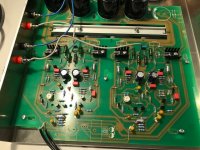
what i can say is that a Chinese pcb of nap 140 with the real components, the good psu and the good settings sound like naim.
what is immediately obvious is the black curtain behind, typical of the naim sound.
the voices are ahead and the instruments are well distributed.
I tried it with a NAC 42.5, a small buffer / preamp tube EF95 and a nakamichi 410 and a cd player philips 471 tda1541 NOS hacked.
for me the best result is live with the philips and just after, on the little preamp / buffer ef95
Can't be the right schematic. I just count the amount of the transistors. On my PCB are 15.
Three more than in this schematic....
Three more than in this schematic....

originale nap 200
An externally hosted image should be here but it was not working when we last tested it.
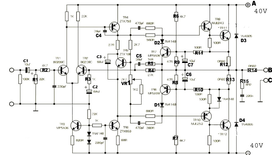
Very nice. But that will not answer my question if it is ok the the Transistors ZTX753 & ZTX653 are getting hot ( around 60°C). Is there a manual available for the adjustment procedure or a nap200 schematic?
Very nice. But that will not answer my question if it is ok the the Transistors ZTX753 & ZTX653 are getting hot ( around 60°C). Is there a manual available for the adjustment procedure or a nap200 schematic?
There are lot of discussions about nap200 clones here, you need to spend a good amount of time to read them, I believe many of your questions have already been answered in the past. Check posts around years 2015-2016. If amp is working, there is no reason to think that they were installed incorrectly, otherwise they may have blown already. You may want to find NOS versions of those transistors, your versions are probably cheap Chinese versions.
find yourself in relation to the diagram. to control the transitor pin, you need a transistor tester or a multimeter equipped with this function
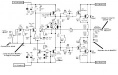
Because these have some protection (Extra BJT-s) I did remove those and it sounds much better! Of course, you should use speakers protection. At least highly recommended.
Attachments

I can look in my archives, I do not find this scheme has fifteen transistors.
I know this generation well, so I do not understand
I know this generation well, so I do not understand
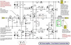
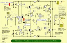
This kit should have its own thread by now. The NAP 200 is not the same as older NAP designs . Earlier here, more than a year ago when the NAP200 kit was new, member algar_emi reverse-engineered the schematic and posted hand-drawn diagrams. I'm not going to search for it again but the pics of the kit are large format and can be easily identified among other posts about NAP140 kits.
NAP designs always have VI limiter circuits for protection, i.e. TR6,7 on the various generic type schematics shown in post #2797 above. These are the only form of protection specified and Naim never used relays for good reasons - regardless of the generalised objections to limiters affecting the sound. The NAP200 is a newer design, developed with some advanced PCB layout techniques and dual slope VI limiters which more closely follow the curve of the specific original types of power transistor's Safe Operating Area. They are a 2 transistor design here, applied to both positive and negative output voltage swings. That's why you find 15 rather than 13 transistors in each power amplifier. The limiter transistors marked and supplied with my kit by Caowei are 2N5087/5089. I don't know how other brand PCBs are marked but these are not critical parts and the originals may have been MPSA06/56 which are obsolete.
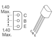
Re: alignment of ZTX653/753. Look at the PCB and note the shape of the transistor outline which should have a flat side and a side with a radius to each side edge. Compare this with the standard E-line package transistor outline and your eyes or sense of touch will tell you which way is the correct alignment. (also see attached diagram which the same for either type).
If you need to know the pin assignement of any transistor, simply type the part number followed by "pinout" into your browser's search engine. Barring the possibility that some manufacturers messed with this on a number of BC (Prolectron series) transistors for their own reasons - it works for me and takes very little time.
NAP designs always have VI limiter circuits for protection, i.e. TR6,7 on the various generic type schematics shown in post #2797 above. These are the only form of protection specified and Naim never used relays for good reasons - regardless of the generalised objections to limiters affecting the sound. The NAP200 is a newer design, developed with some advanced PCB layout techniques and dual slope VI limiters which more closely follow the curve of the specific original types of power transistor's Safe Operating Area. They are a 2 transistor design here, applied to both positive and negative output voltage swings. That's why you find 15 rather than 13 transistors in each power amplifier. The limiter transistors marked and supplied with my kit by Caowei are 2N5087/5089. I don't know how other brand PCBs are marked but these are not critical parts and the originals may have been MPSA06/56 which are obsolete.
Re: alignment of ZTX653/753. Look at the PCB and note the shape of the transistor outline which should have a flat side and a side with a radius to each side edge. Compare this with the standard E-line package transistor outline and your eyes or sense of touch will tell you which way is the correct alignment. (also see attached diagram which the same for either type).
If you need to know the pin assignement of any transistor, simply type the part number followed by "pinout" into your browser's search engine. Barring the possibility that some manufacturers messed with this on a number of BC (Prolectron series) transistors for their own reasons - it works for me and takes very little time.
Attachments
Member
Joined 2009
Paid Member
In my NAP 160 clone I have taken the opposite approach. I view the amplifier VI limiters as being an old solution to protect speakers where unreliable mechanical relays were the only choice and avoiding dc on the speaker was mostly about avoiding the output devices from blowing up - hence protect the output devices and the speakers are a bit safer. The newer solution is to use dc protection at the output of the amplifier using solid state relays - and toss out the VI limiter which is not quite an ideal solution to start with.
- Home
- Amplifiers
- Solid State
- NAP-140 Clone Amp Kit on eBay