If you are going to have C10 you'd better have C11 too. But based on your circuit board photo I wouldn't add either. Just make sure you are using good quality PSU caps and your wire runs to the PCB are nice and tight.Is C11 a bad idea?
[/IMG]
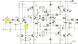
A couple of easy changes that should make it sound better:
Use a polystyrene 56pF cap (next to Q4) instead of a ceramic.
Use a bipolar cap for C3 (or at least put the existing cap around the right way: + to gnd).
NOTE: Almost all the Naim power amp schematics I've seen on the web continue to have the feedback dc blocking cap the wrong way around. I have no idea who started this mistake but it seems to keep on going. Including in the schematics just pasted here. The +'ve terminal should go to gnd because the LTP base voltages will be slightly negative.
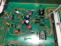
It's very tidy. Note they have put the main PSU caps on the power amp board with the star ground there. They haven't put smoothing caps elsewhere in the case with a second set of caps on the board which is what some of these kits encourage.i love the nait 3 !
Yes, that's the Nait2 schematic that I referred to. There are some more drawings for the preamp section and power supply if needed, since it's an integrated amp. The power supply is +/- 30V for NAP90 and +/- 22V for the Nait2 so you need to adjust parts ratings and probably some resistor values that set bias currents in the front end such that they are correct for your actual supply voltages.the nap 90 is the same to nait 2,3 and probably the 5 ....
Last edited:
what cap ? 😕NOTE: Almost all the Naim power amp schematics I've seen on the web continue to have the feedback dc blocking cap the wrong way around. I have no idea who started this mistake but it seems to keep on going. Including in the schematics just pasted here. The +'ve terminal should go to gnd because the LTP base voltages will be slightly negative.
@ Ian
yes !
I was gone on a 2x33vac transformer because I had it in stock but I will look for another 2x24vac to be closer to the origin nait / nap
yes !
I was gone on a 2x33vac transformer because I had it in stock but I will look for another 2x24vac to be closer to the origin nait / nap
Member
Joined 2009
Paid Member
A couple of easy changes that should make it sound better:
Use a polystyrene 56pF cap (next to Q4) instead of a ceramic.
...
I've not tried a polystyrene cap, but I have used both silva-mica and npo ceramic. The ceramic performs superbly
Don't run decoupling capacitor leads to a remote PSU Zero Volts.I've been looking at that decoupling mod for the Nap140 too and have gotten me some low ESR Panasonics rated to 50v to test.
Is C11 a bad idea?
(The schematic is from the Acoustica mod list).
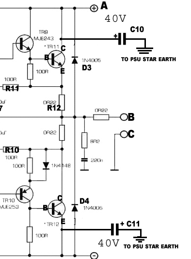
Join the two decoupling caps together with the shortest possible leads and take the Speaker Return to that junction. Take the Amplifier Output Zobel to this same junction.
Finally run a wire from this junction back to the PSU Zero Volts inside the twisted triplet that brings power to the PCB.
Last edited:
If it's an actual NAP140 or other superseded Naim product, you wont find twisted leads of any description.
Probably to save money. 😀If it's an actual NAP140 or other superseded Naim product, you wont find twisted leads of any description.
I once met somebody from Naim, I think it was Paul Stevenson, or JV himself. I asked him about the cable trees within the amplifiers, and he told me a very nice story about the lady, who made the "trees" so neatly - she treated them as a piece of art, not electricity, just formal precision and pretty colors. They had some problems after she retired.
I further asked why the wires were not twisted, and he answered something like "not necessary because of low impedances".
But this happened now more than 30 years ago, and my memory might be fooling me.
I further asked why the wires were not twisted, and he answered something like "not necessary because of low impedances".
But this happened now more than 30 years ago, and my memory might be fooling me.
Member
Joined 2009
Paid Member
Try a polystyrene or teflon or polypropylene at a pinch. 🙂
I avoid other dielectrics.
Why avoid modern npo, they have excellent performance, not Teflon maybe but they compete everywhere else ?
ceramic capacitors ?
Why not NP0/C0G caps?
Ceramic capacitors in audio signal paths
Last edited:
i should receive my mie 243/253 today to finish my 90 and make the first comparative tests with nait 3.
the only difference will be the 39pf, all the rest will be identical including the ztx 108 replaced by a bc108.
to be continued...
the only difference will be the 39pf, all the rest will be identical including the ztx 108 replaced by a bc108.
to be continued...
NAP200 Clone up and running but a question
Hi guys,
nice forum.
I build a NAP200 clone. It is up and running.
But Iam afraid that something is wrong. The Transistors ZTX753 & ZTX653 are becoming "warm" I think they will reach a temperature of about 60°C.
Is this normal?
Is it possible that the AMP is oscillating?
Many thanks for you're help.
Best regards from Germany
Attachments
check the pinout of the ZTX (BCE/CBE)Hi guys,
nice forum.
I build a NAP200 clone. It is up and running.
But Iam afraid that something is wrong. The Transistors ZTX753 & ZTX653 are becoming "warm" I think they will reach a temperature of about 60°C.
Is this normal?
Best regards from Germany
I have used all the supplied transistors from the kit. The supply voltage is 25-0-25 VAV from one transformator.
Ok. I have the data sheet. But on the PCB is not printed BCE/CBE. How can I check if the Transistors are soldered correct?
Ok. I have the data sheet. But on the PCB is not printed BCE/CBE. How can I check if the Transistors are soldered correct?
- Home
- Amplifiers
- Solid State
- NAP-140 Clone Amp Kit on eBay