Is high current like 4-5v over one 0r22 and is immediate. Single difference so far: for Vbe multiplier in not working channel I have 2n5551 and the working one Tip41. I will recheck everything this evening as yesterday got mad and went to sleep 🙂
Sent from my Nexus 5 using Tapatalk
Sent from my Nexus 5 using Tapatalk
I have received 2N5551/5401 Chinese transistors with different pinout (ECB) to US type (CBE) before but you may have checked that possibility already. The fault would have to turn both output transistors full on to get that much current (about 20A) so you may need to look at what drives them or even a shorted track or wires as possible faults. That current is more than the transistors and PCB tracks can handle. Your power supply must be huge to cope with that and there probably aren't any fuses that could withstand that!!
Perhaps you should use a bulb limiter before you smoke more of your good parts.
Perhaps you should use a bulb limiter before you smoke more of your good parts.
Most probably the pinout is wrong. I use for this phase a +/-45 v 500w smps.
Sent from my Nexus 5 using Tapatalk
Sent from my Nexus 5 using Tapatalk
One thing Andrew said that I might want to show in a different light. Andrew thinks of the Naim as being a musical instrument in it's own right. Yes and No with No being the stronger arguement. Douglas Self will say any distortion we don't need to have is wrong. Jean Hiraga will say an amplifer with unfortunate harmonics is wrong. Most amplifers fit the wrong by Hiraga model. The PP valve designs the worst of all if typical.
What Naim have done is what engine designers do. That is make the balance factor of the engine suit cruising at legal speeds. That was often 55 MPH if the USA.
Some Rover engineers got into trouble with BMW. The Rover guys analysed the BMW 6. It was found to be very much like a Naim. This was using the Honda pakage they had. If asked to choose Honda or BMW as much as I like Honda I would say BMW know the game they play. If something isn't for enjoyment what is it for. To be honest the Naim NAP 250 would not sound better to be made into a Self amplifier. If anything it needs to be warmer sounding. The valve amp I gave the other day looks identical to the NAP 250. Except the Naim is 40 dB lower down. BTW, no human can hear - 80 dB. I wonder if Mr J V imagined it ? His staff did the mod which made J V more confident ?
Naim are bought for their reputation for the sound that they reputedly make.
I would imagine (maybe incorrectly) that anyone making a Naim clone can only be doing that to achieve the Naim sound.
And if they like that, then success.
I have listened to Naim demonstrations at my local (no longer in business) Naim Dealer and never bought any Naim equipment.
But I did ONCE hear a fabulous Naim/Linn demonstration.
The Linns were activated and there were six channels of big Naims, way out of my league.
They had a Linn/Quad on demo at the same time but it was so busy in there that I could appreciate the quality, even from the back.
Naim are designed to make that Naim sound because it sells Naim amplifiers.
Last edited:
I think it is all over done. I am sure if a Quad 405 had a larger Naim PSU and it's protection made less wonderful the sound of the two would not be far apart. 405 and 303 invert so always factor that in. That is a much larger difference if wrong. Drums should only kick backwards if the engineer wanted it ( Beatles ?? ). Naim transformers were made in Scotland by Holden and Fisher if I spell them right. They were supurb. The 33 inverts also. This makes the 33/303 correct phase and avoids any extra components ( to my way of thinking one less stage used , it almost seems to have too few until each is evaluated ). The 303 is able to invert without a low resistance input. A very interesting design. I have come to learn 33/303 if understood can sound second to none. It's also like Naim in it's special sound ( not identical ). You have to believe it can do what you want and build speakers etc to suit. I think this is where to wan't better is most likely to be to suit mismatch better ( the usual case ). Nearly everything in the modern world will mismatch a 33/303. Resolve that and to say it is wonderful is to just touch the surface of how good it can be. The Quad has a slightly better version of the Naim harmonics. It is how a single transistor works. The 33/303 has a very narrow window of correct level matching. It needs carefully adjusting for gain to get it right ( +/- 3dB I would say ). As a rule of thumb make the sound level the same as good FM via an FM3. Sadly the 33/303 was always like this. A Naim would eat it for breakfast if the mismatch was " encouraged ". Someone did a lengthy upgrade of 33 only to think Quad got it right at the end. His advice was to upgrade some capacitors and accept the overload margins as being a bit low. On pick-up's take you time. The 3 dB difference is that between OK and excellent. The sound will be punchy and open if right. DL 110 almost suits the M1 board. I totally redesigned the RIAA of the 33, only to find Quad did an excellent job. It's one of the few active RIAA I like ( inc 75 uS that is ). OK it is not the most accurate. That isn't the question as no pick-up is either. Far better simplicty that works than correct design that subtly doesn't. I prefered it to a better type NE5532 design.
Last edited:
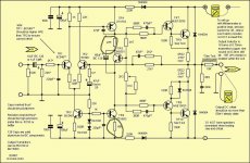
This is my build from the hand draw sketch that I built in 1990.


msdin
Nicely built amp! Those power transistors are great🙂🙂
As i said second channel of my Naim clone turned to be malfunctioning measuring aprox 4V across the two 0R22 emittor resistors.
Followed the advice from Ruwe from post #214:
"9.Measure the voltage across the 100-ohm resistor between the base and emitter of the top output transistor (Remember, you still don't have the output transistors on the boards). Turn the trimmer and set this voltage to be small: 0.25V-0.30V, or less if possible, is fine. Now you can safely connect the power transistors and they won't have dangerous currents through them. They shouldn't have current at all in this situation."
So i removed the power transistors and on power on the 27R and 68R from VAs smoked out very fast.
Measured with DMM all semiconductors and VAs resistors, everything looks good. So frustrating as this amp looks so simple and still making this problems.
Any advice please ?
Adrian
Attachments
Last edited:
I think solved the mistery somehow, long story short the VAS transistors wrong soldered.
Now without speaker connected i can adjust bias and it stays stable BUT after speaker is connected bias goes very high and it becomes unadjustable, no matter the position of potentiometer i measure areound 65mv across both 0r22 resistors meaning 145mA of bias.
What could be the reason of this high bias with speaker connected ?
I think solved the mistery somehow, long story short the VAS transistors wrong soldered.
Now without speaker connected i can adjust bias and it stays stable BUT after speaker is connected bias goes very high and it becomes unadjustable, no matter the position of potentiometer i measure areound 65mv across both 0r22 resistors meaning 145mA of bias.
What could be the reason of this high bias with speaker connected ?
Hi,
Checking this circuit bias without the power transistors is always good idea and saves money for new power transistors 🙂 Without conducting Vbe multiplier transistor, the whole VAS current goes through the resistors 2.7k+trimmer, which corresponds to some 25V bias for the drivers+output transistors. That will turn them on very, very hard.
When you measure 65mV, what is the DC offset (output to ground)? What is the offset without the load?
I would check the feedback capacitor for short. It seems that the feedback works differently with and without load. Maybe, when you smoked the board the first time, large DC offset appeared on feedback capacitor in reverse to its polarity and blew it... That's very general suggestion, though... You may have something else failing after the initial smoke, but it's hard to tell without proper troubleshooting and/or more details.
Hi,
I would check the feedback capacitor for short. It seems that the feedback works differently with and without load. Maybe, when you smoked the board the first time, large DC offset appeared on feedback capacitor in reverse to its polarity and blew it... That's very general suggestion, though... You may have something else failing after the initial smoke, but it's hard to tell without proper troubleshooting and/or more details.
The amplifier should be stable if the integrity of the feedback network is not compromised. If the feedback cap has gone open circuit and the bias cannot be set it will be oscillating due to that cause.
The amplifier should be stable if the integrity of the feedback network is not compromised. If the feedback cap has gone open circuit and the bias cannot be set it will be oscillating due to that cause.
I agree, but I think feedback capacitor shorted. Typical for tantalum that he has on the board.
Thanks for help !
The feedback cap was transformed into a 40 ohm resistence and the 10ohm resistor between spk gnd and input gnd was transformed into a 1k resistor.
Now i have stable bias and around 20mV of DC out.
Is there any other possibility to check for any oscillation and instability without a scope ?
When testing and measuring with spk connected without input source connected or shorted when touching input cap the zobet 8R2 resistor gets hot even smoking a bit. Is that normal ?
Last edited:
The NFB lower leg capacitor normally sees a tiny AC voltage and a tiny DC voltage.
Even when producing clip free maximum power.
But if an output offset that goes to a high DC value that capacitor will see a high DC voltage.
To prevent damage during this fault condition, one can use a diode across the capacitor to prevent that reverse voltage.
If one prefers one can use two series diodes to double the maximum reverse voltage to ~ 1.4Vdc.
One also has the option to add a diode in the opposite direction to limit the maximum forward voltage across the NFB capacitor.
I use a pair of inverse parallel diodes across my NFB cap in every amplifier I build. That limits the maximum voltage that the cap can see to +-0.7Vdc
You can use 63 V non polar caps. They have a good reputation when compared with so called Audiophile caps.
One thing I notice is the TR9/10 have no local decoupling caps in diagrams. A value between 220 to 2200 uF ( 63 V ) can only do good. There was a discussion on this sometime ago on another thread. 2200 uF was thought to be a nice big value to have. It can be a high grade. It was found using a cheap capacitor of good ripple current in the main PSU was a virtue. The losses of the cheap caps and the wiring then are part of a filter. I can see that might work.
One thing I notice is the TR9/10 have no local decoupling caps in diagrams. A value between 220 to 2200 uF ( 63 V ) can only do good. There was a discussion on this sometime ago on another thread. 2200 uF was thought to be a nice big value to have. It can be a high grade. It was found using a cheap capacitor of good ripple current in the main PSU was a virtue. The losses of the cheap caps and the wiring then are part of a filter. I can see that might work.
First Naim Clone with Smps 🙂
Sent from my Nexus 5 using Tapatalk
An externally hosted image should be here but it was not working when we last tested it.
Sent from my Nexus 5 using Tapatalk

This is a Hypex SMPS. I was a little surprised it wasn't quieter. Where I work we have a specialist designer who can make SMPS. What I proposed was to synchronise the SMPS with the Hypex self oscillation. My engineer said what I really meant was could we use a Linear PSU. I said that was possibly what I was asking. What I really hoped for was to use multiples of the 400 kHz and have then locked together.
The effects of the Hypex SMPS was to make it sound brighter ( UCD 180 ). The Hypex sound is very nice, it made me fight on to a solution. The one thing the SMPS did give was a sense of great power .I did have some graphs of SMPS verses conventional under a file name I can not remember.
Notice how there is some ripple. Hypex exspect the UCD 180 to deal with that. It's not bad. This is into a Hypex module on idle.
Now i have stable bias and around 20mV of DC out.
Is there any other possibility to check for any oscillation and instability without a scope
When testing and measuring with spk connected without input source connected or shorted when touching input cap the zobet 8R2 resistor gets hot even smoking a bit. Is that normal ?
You have an insipient oscillation issue to resolve - try touching the stability cap in the feedback network with your finger. This should add a little parasitic capacitance. The expiry of the tantalum cap may have generated a voltage spike. Repeat the touch test with the Vas cap to see if this cools the zobel resistor.
The feedback cap was transformed into a 40 ohm resistence and the 10ohm resistor between spk gnd and input gnd was transformed into a 1k resistor.
When testing and measuring with spk connected without input source connected or shorted when touching input cap the zobet 8R2 resistor gets hot even smoking a bit. Is that normal ?

Two things about tantalums: they don't tolerate reverse voltage of more than 1.0-1.5V and they always die with a short.
I don't know exactly the components' values on your schematic. Do you have the same behaviour on both channels or only on the blown one?
If only on the blown channel: check the VAS capacitor, although I don't think it's damaged. Also check the one in the feedback (the small one - 47pF or whatever you have there).
If on both channels: You probably have borderline oscillation condition. Meaning that your VAS capacitor may be too small or most likely, from my own experience, your driver transistors are not suited to the job. My recommendation is for MJE243/253. I also know that TIP41/42 works OK. Many of the other popular driver transistors have combination of parameters not suitable for this circuit.
Have in mind that most amplifiers will produce horrible noise if you touch the input with your finger, for example. I don't know what DMM you're using, but it's possible the probe to excite the input exactly the same way. If the frequency is high enough the Zobel network is taking all the load (without the speaker), thus the Zobel resistor becomes the load.
What is the power rating of the Zobel resistor? It must be at least 3W if you want it in the circuit permanently.
- Home
- Amplifiers
- Solid State
- NAP-140 Clone Amp Kit on eBay