Hi Ruwe, more direct experience with the actual circuit does wonders for sanity.
If we read Self on current imbalance in the relevant input stage chapter, its clear by experiment that if the LTP loses balance, even by 2% in either leg, H2 distortion quickly increases by half then to as much as 0.5%THD or so with lesser proportions of higher harmonics. Transconductance also increases. However, as I have noticed, this can be overshadowed in the practical Naim circuit, by H2 generated in the VAS.
ref: 6th ed. APAD by Self, chapter 6.
H2 is not all that noticeable, as Nigel suggests, given that some higher harmonics are present too in diminishing proportion as Jean Hiraga advocated. It's easy to ignore this type of distortion if you like the effects (Naim's Pace, Rhythm, Timing shtick for example)
I haven't yet looked at any of that for myself with appropriate instruments. Perhaps I should but it is not simple to prove anything when we are attempting to compare apples and oranges circuits, modified circuits, components, power supplies, products and whole technologies even, all at once.
As an aside, we can see even in Vereker's circuit just posted, that simply omitting the TR2 collector resistor was considered as it doesn't contribute to balance. Some still don't get it 😉
Roender and others adopt it....................I have never seen a Cascode CCS..................
It vitually removes Early effect from the CCS transistor. But it needs more voltage drop.
It does contribute to balance. By balancing Vce and Tj. It's not just about balancing Ie.......................
As an aside, we can see even in Vereker's circuit just posted, that simply omitting the TR2 collector resistor was considered as it doesn't contribute to balance. Some still don't get it 😉
BTW,
how are any one checking balance of Ie in the LTP?
There is no mechanism in the circuit to allow measuring of the two Ie relative to each other.
Last edited:
Hi Ruwe, more direct experience with the actual circuit does wonders for sanity.
Yes, totally agree.
I read Self religiously through the years 🙂
When you play with the audio circuits though, you often find that most of the theory is just a theory after all. I'm sure the figures are great, and as Self says many times in his book, the figures sell the product. Because what else customers have to compare and choose from?? ... Few watts more for the same price, and you already have an advantage.
I experimented a lot with most of his ideas, and unfortunately with this circuit they don't add any additional magic to the sound. I don't think Darlington style VAS will sound better, or symmetric VAS, or LTP matched within 1%, or diamond buffer or output triples etc... I'm sure it measures better/differently, but I'm sorry - I don't hear it 🙂
To me, one part of this amp that is often overlooked is the dynamic bias change due to sudden change of the output/driver transistors junction temperature. Self wrote a lot on that... I'm positive that the clone circuit is not optimized. Especially, considering the large variation in transistors that DIY-ers use. Strangely, nobody questions that 27 ohms resistor in the voltage multiplier 🙂
Is it too much or too little for your output stage?! What about the voltage multiplier position - stand alone, or on drivers heatsink or on output transistor heatsink?! When you listen loudly and then you suddenly stop and measure the bias: is it higher, lower or same as before? If same - that's jackpot ....
I remember few years ago, I went crazy and built the output stage with Lat. FETs just to avoid the thermal drift and make sure that I have squeezed the maximum from the input topology. Sound was not bad with about 150mA bias in the FETs, but generally I was not trilled, nor I heard some groundbreaking improvement. The circuit became even simpler, that's the only positive.
... The hand drawing, if really Julian's, is very basic version. It seems more like design idea, than actually working or tested circuit. I can't take it seriously, but if someone believes that all Julian's work is one of a genius, I want to know more. I've heard of crappy sketch on a napkin selling for hundred thousands dollars, because it was Picasso who was doodling... Who knows?!
My opinion, as always, is that the circuit is good "as is", and that it can be improved with better components, better power supply and proper grounding. Those three also suggested by Naim in their documentation. They say nothing about improved circuit, for example, in their upgrade options.
Just my opinion...
The drawing is real and it was the circuit for the NAP 125 & NAP160 both were up dated over time with different devices.
I got the circuit from Julian after a meeting with a friend Barry Porter who has now past away.
There was also another drawing that look similar but with a mosfet out stage.
Julian asked Barry if the circuit would work with the Hitachi mosfet, Barry said that mosfet design was too basic Julian's reply was I'll leave it up to you to come up with something.
Two weeks later Barry's design was finished, the circuit had six or seven more transistors and a op-amp in a servo loop.
The follow-up phone conversations with Barry and Julian did not go very well, Julian said that the new design lost the sound that he was looking for!!
msdin
Last edited:
That's funny, Julian asked me if I could source MOS FET's when I first met him. When I get a moment I will show how that could be made to work using the Naim kit.
Here for interest I have sketched a Cascode CCS. Depending on exact circumstances the collector impedance can go from lets say 100 K to 30 M ohms. One could be very simplistic and say it's compound gain doing the magic. The ideal current source is like an infinite resistance. When we say Long tail pair we mean the tail goes to infinity. This was more the case when valve voltage amps. If you own a typical one of those often the anodes are at 100 K and 91 K as the tail is very short. If the 2 x EF 86 of a Quad power amp are fed buy a new - ve power supply on a current sink this can be put right. To give you an idea of how good this can be. An ECC83 valve on a Cascode CCS can swing 7 Vrms at 0.04% THD without any loop feeedback. As the ECC83 can offer a gain of 100 it could put a OPA604 to shame. As transistors that avoid Early effect ( try ) are near perfect current amplifiers the improvements they bring are truely as if they were resistors. Valve people usually won't touch these circuits. That's bonkers. As I have just shown a valve can be a device that beats all others. Even hiss will be low.
The Long tail pair input of the Naim is clamped by the VAS at 0.7 V ( circa ). Thus the funtion is no longer a voltage amp. The reason to use a current source is mostly to gain a small advantage in noise rejection. It is very very small where we really need it at lets say 50 kHz, the Naim design is about the same as a resistor at that point. It is possible that a resistor could sound better. Simulations of a similar amp showed rejection about 30 dB better up to 20 kHz. Above that 90 dB for either resistor or CCS. Both are very good considering how dirty that end of an amp is compared to having it's own PSU
The second CCS using 91R is with a voltage amp ( or I to V converter some call a TIS ). This would be exspected to have a lower distortion.
I don't advocate using this Cascode idea. It's just to show it could be done without drastic changes. The upper transitor can be something really nice like BF720. I have used 2 Red LED as they should just about do the job with least loss of voltage swing. 1960's cascodes often had small resistor ( 33R ) between the two device. If so the voltage loss needs to be increased to take account of it. I notice this has past into history. The upper device is a common base amplifier. The resistor is to improve lineariy as it would if a long tail pair.
Now the practical/useful part. A Cascode will not cope with noise as well as the original circuit. The 22K resistor is replaced with a JFET. Vishay have very fancy ideas about the price of these. The one I show from Rapid UK is about $1. It will help this circuit to work.
The news of note is all of these kits amps could use this JFET ( CRD ). It is 2 mA which is perfect. Whilst I did slightly knock the idea of these previously this is different as it is just acting as a CCS and it not involved directly in linearity. Be careful to fit it the right way around as it will work backwards and give goodness knows what results. Keep it in it's own draw as it looks just like a 1N4148. I doubt these will exist for much longer. To swap one 22K resistor for one CRD is the easiest modification ever done on these kits. The black line to the negative. It won't change the Naim sound balance. It will just make this part of the amplifier more stable and perhaps quieter. JFET's with voltage references are the circuits of first choice in many text books. The simplest is the best.
I sat in bed last night and asked myself what I had really invented in my life. Mostly nothing as it is something I've seen in one place and transported into my design as how I did it.
Somehow this story about this amplifer seems to include a lie. That lie is who designed the NAP? Bob Widlar is my best guess or H C Lin. Both worked on early op amps of which Naim is one. Some say op amp style power amp. The 741 seems to have been stolen from Mr W in 1963. H C Lin also was doing similar work. Op amps date back to at least 1935 and Alan Blumlein.
I was asked by a Mr Posner " Young man do you tell lies " ? My reply, " Yes, the ones I am told ". He smiled and said he father would have said the same.
People always tell me " It is a fact " to which I say " Were you there " ? The Naim story is not unlike the Bible. We have to trust no one is bending the truth. In hi fi many of us do it for it's simplicity of being the truth. Allowing for taste the rules are defined and can be argued. We mostly don't make leaps of faith. And if we do it works or doesn't work as proof.
Regardless of how good my modifications are I have come from nothing to something in a day. Julian Vereker didn't and to me that says he was no different to a hobbist. I have total respect for what he did. I can not believe he really designed any part of the amplifier. That is no disgrace, a boss who can help design is a great thing. More so a boss who can direct the process. I guess the Cosworth V8 was no different? A 1916 airship engine being similar. A company I worked for, our lathe man worked for Keith Duckworth. Stupid thing is I could have delivered the parts if I had thought about it. I never did.
Last edited:
This is the FET output circuit that I tried. I don't think it contributes anything special and I was not sure that I want to post, but it really doesn't matter.
I can only guarantee that it works perfectly just as the original clone.
I don't claim it is better, or that it can't be improved.
As I said, I just wanted to try the front end without the gm doubling and the thermal discrepancies at the output.
You can also see that the hi-frequency behaviour is better. 50kHz squares are pretty good, especially compared to the original.
View attachment NaiMOS.pdf
You may be assuming that precision was the aim here, but I think the question is rather how far from balance were the commercial products? No one has even mentioned emitter currents or junction temperatures yet. That would be taking audio design considerations forward 10-20 years from the first NAP designs. Even Self's analyses, which are what I referred to and quoted from, only consider tail current and leg collector current balance. In any case, it remains a rather crude design where precise balance is unlikely and I think undesirable.It does contribute to balance. By balancing Vce and Tj. It's not just about balancing Ie......BTW, how are any one checking balance of Ie in the LTP?....There is no mechanism in the circuit to allow measuring of the two Ie relative to each other.
The drawing is real and it was the circuit for the NAP 125 & NAP160 both were up dated over time with different devices.
I got the circuit from Julian after a meeting with a friend Barry Porter who has now past away.
There was also another drawing that look similar but with a mosfet out stage.
Julian asked Barry if the circuit would work with the Hitachi mosfet, Barry said that mosfet design was too basic Julian's reply was I'll leave it up to you to come up with something.
Two weeks later Barry's design was finished, the circuit had six or seven more transistors and a op-amp in a servo loop.
The follow-up phone conversations with Barry and Julian did not go very well, Julian said that the new design lost the sound that he was looking for!!
msdin
He should have asked John Farlowe 😀
The classic Exposure amps were effectively a Naim front end with lateral FETs.
You may be assuming that precision was the aim here, but I think the question is rather how far from balance were the commercial products? No one has even mentioned emitter currents or junction temperatures yet. That would be taking audio design considerations forward 10-20 years from the first NAP designs. Even Self's analyses, which are what I referred to and quoted from, only consider tail current and leg collector current balance. In any case, it remains a rather crude design where precise balance is unlikely and I think undesirable.
I accept that Naim turned their amplifier into a music instrument, because that gathered them extra sales.
My reply was ONLY to correct the statement made that
In a balanced LTP the two devices must have the same operating conditions. Then when the current is accurately balanced, the LTP gives the best performance, i.e. lowest errors.TR2 collector resistor was considered as it doesn't contribute to balance
But that balance REQUIRES all the operating conditions to be matched/balanced.
Some just don't get that !
All this OCD balancing is all well and good but some seem to forget the loading of the VAS base current. Selfie certainly does in his 1993 Wireless World article.(fig 7c on page 734 if anyone is interested), indeed his favoured current mirror technique actually forces a significant imbalance because it "ignores" the likely 50 - 100uA VAS base current of the VAS.
So, if you want "perfect" balance in the NCC200 LTP then you need to load TR2 with 1K in parallel with the BE junction of another ZTX (running at the same current).
Personally, I don't worry that much about it. Low PPM distortion at high signal levels does is not necessary for good sound IME (although it does no harm).
I accept that Naim turned their amplifier into a music instrument, because that gathered them extra sales.
My reply was ONLY to correct the statement made that
In a balanced LTP the two devices must have the same operating conditions. Then when the current is accurately balanced, the LTP gives the best performance, i.e. lowest errors.
But that balance REQUIRES all the operating conditions to be matched/balanced.
Some just don't get that !
Something like these?🙂
Attachments
Listening to Naim amps today I find them very unremarkable. I love the way they were made. Somehow speakers have changed. I asked Spencer Hughes of Spendor what amplifer he prefered ( circa 1982 when he was very ill ). He said he should prefer Quad as they were old friends, he prefered Naim. He said people assumed his speaker to be an easy load. His exact words to me. " If I was an amplifer looking down the speaker cable with binoculars I wouldn't see drive units in the BC1. I would see chokes and capacitors. I would say I'm going home and not bother ". It is perfectly possible from KEF to Linn most speakers of the day had the same design problems. Not in the external but the Spenser binoculars. The Naim amps super tuned to the reality of the day. The speakers also super tuned to best of kind. I have some Dynaco A25. I think I should try them with NAP 250. I have a hunch it could work very well. NAP 250 in it's day was very fast sounding. Now it sounds nice enough. The NAD 3020 put up against it wasn't completely pushed to one side. I would side with Andrew and suggest some experimentation as J V did. The design should have very good devellopement potential. The all NPN output stage I suspect is doing nothing to put it in doubt. Everyone should have a NAD 3020. It is a good preamp, a good power amp and an OK pre-power. Buy two to make a pre-power. I use a NAD to stand in for a pre or power amp when testing things. It seldom is beaten by things many times it's price, especailly when just a preamp.
Your circuit shows the LTP as having emitter degeneration resistors.Something like these?🙂
You can use these to check and/or set up the LTP current balance by measuring and adjusting for zero voltage between the LTP emitters.
Once this is done, you will find that the VAS current injected into the left side of the LTP is taken into account.
Now check the difference in collector voltages of the LTP and while you are at it check Vce.
If Vce are equal and Ie are equal and hFE are equal and Vbe are equal (these last two require matched devices), then you find that Pq are equal. Now you have a balanced LTP.
That is clearly NOT what Naim require.
The Vbe multiplier is still the wrong way round.
The D.Self explained resistor 27r above C3 is there, but it can't work properly since the multiplier is connected incorrectly.
Last edited:
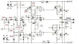
Started my quest to the NAim clone project (little late i know) and followed in the first phase the NCC200 schematic.
First channel worked great from the first with around 10mV DC output but the second one gave me a little smoke from the 0R22 emittor resistors as i measured around 4-5V over them so i need to troubleshoot a little in order to make it working.
Some of the caps are not the recommended ones, installed what was available for the moment better ones are on their way to me.
I use BC546 for input, ZTX for VAS (working a bit too hot) MJE15034/35 for predriver and NJL0281 for power (recicled some thermaltracks from an old project).
An externally hosted image should be here but it was not working when we last tested it.
Last edited:
AndrewT, I was talking specifically about the hand drawn Naim design which is in partial balance, and you are talking about the general case of optimally balanced LTPs. However, if you read the reference to Self I made with that comment, you'd see the situation here is much as I said. I don't mind being corrected for blunders, but not on a misunderstanding.
You have indicated that you have a copy of APAD 6 so on p129 ff regarding input stage balance and at figure 6.7b, is the circuit diagram and the resistor in question which:
As a matter of interest, I've done the experiment and related work on Naim and clone input stages many times - shorting the 22k TR2 collector resistor does do almost nothing. You can easily establish DC balance without it as was the case with the clone I tested and a simulation I posted here. DC Balance can be adjusted by trimming TR1 resistor (2.2k in the sketch) but feedback overrides any adjustment of TR2 resistor (where fitted) within its functional current range. That's why it is redundant as far as DC balance is concerned. It is relevant though, that the stage is operated at quite low tail current.
I consider a simple, visually balanced LTP with equal collector resistors as a poor cousin of the LTP with current mirror. The main points for audio of best LTP balance though, is that you can say it cancels 2nd harmonic distortion most effectively, stabilizes DC offset and generates little distortion of its own. Some would also say that reducing H2 selectively is a bad thing and a singleton or CFA amplifier design makes a better audio listening proposition regardless of increased overall THD. You don't have to look far on this forum to see examples of the serious interest there.
You have indicated that you have a copy of APAD 6 so on p129 ff regarding input stage balance and at figure 6.7b, is the circuit diagram and the resistor in question which:
I think we could consider the "very little" contribution more appropriately elsewhere, if that was the basis of your objection.has been excised as it contributes very little to input stage balance
As a matter of interest, I've done the experiment and related work on Naim and clone input stages many times - shorting the 22k TR2 collector resistor does do almost nothing. You can easily establish DC balance without it as was the case with the clone I tested and a simulation I posted here. DC Balance can be adjusted by trimming TR1 resistor (2.2k in the sketch) but feedback overrides any adjustment of TR2 resistor (where fitted) within its functional current range. That's why it is redundant as far as DC balance is concerned. It is relevant though, that the stage is operated at quite low tail current.
I consider a simple, visually balanced LTP with equal collector resistors as a poor cousin of the LTP with current mirror. The main points for audio of best LTP balance though, is that you can say it cancels 2nd harmonic distortion most effectively, stabilizes DC offset and generates little distortion of its own. Some would also say that reducing H2 selectively is a bad thing and a singleton or CFA amplifier design makes a better audio listening proposition regardless of increased overall THD. You don't have to look far on this forum to see examples of the serious interest there.
Hi Atupi. You have fitted the Vbe multiplier to the heatsink as if it were an Emitter Follower output stage but this is a quasi-complementary design where no bias current is really correct. In this design, the bias control transistor does not touch the heatsink and is very slow to respond because it depends on air temperature inside the case to stabilize it at only about 30 mA. Ebay kit instructions usually describe this. Is this an H140 kit PCB?
Your heatsink is very small and you may be experiencing thermal runaway with your arrangement. That will smoke the output stage after some time as the heatsink begins to warm up. Keep an eye on the OK channel continuing to heat up when you are only playing at a steady level.
Your heatsink is very small and you may be experiencing thermal runaway with your arrangement. That will smoke the output stage after some time as the heatsink begins to warm up. Keep an eye on the OK channel continuing to heat up when you are only playing at a steady level.
I know the HT îs small but for testing proved to be enough. After 2 h listening is still cool.
Pcb etched from NeilMcBride project.
Sent from my Nexus 5 using Tapatalk
Pcb etched from NeilMcBride project.
Sent from my Nexus 5 using Tapatalk
- Home
- Amplifiers
- Solid State
- NAP-140 Clone Amp Kit on eBay