Very Interesting that you have chosen this design - and looking very like the original layout. What transistors were used for VAS, drivers and output?
Last edited:
Thank you, the output transistor with BD743C, said that the original machine was erased before the output transistor model is the model, I tried the sound is very close!😀Very Interesting that you have chosen this design - and looking very like the original layout. What transistors were used for VAS, drivers and output?
I see. These were the replacement type suggested by Naim but are now hard to obtain, with no guarantee they will be genuine parts. Did you use ZTX652/752 or ZTX653/753 for the VAS and drivers? They do seem to be E-line package types.
I guess you are quite happy with the sound quality?
I guess you are quite happy with the sound quality?
If you look on the PCB, you will see caowei's name and the HIFIDIY forum (China) logo. I assume then, it is his own DIY clone.
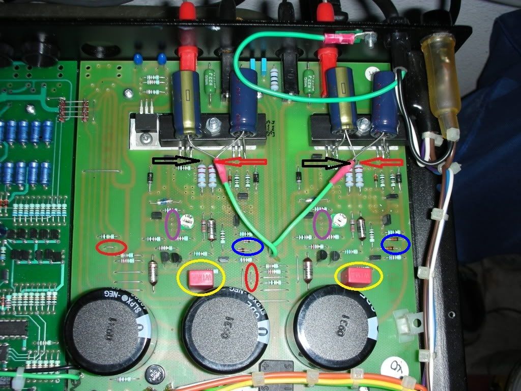
This Pic may help to spot the features, though this one has some unoriginal caps and mods to boost confidence in the 30W output. (PFM)
If you look on the PCB, you will see caowei's name and the HIFIDIY forum (China) logo. I assume then, it is his own DIY clone.
Hello, I meant the NAP140 not the preamp
320622026990 ?
Last edited:
I believe 320622026990 refers to a simplified, modernised design branded H140. It is partly based on NAP 140 but lacks some of its features. The Clone PCB that is otherwise normally available (110577526635), also has incorrect transistors and doesn't sound good either, but at least you can modify it with the correct ones and arrive at similar results and layout to the original, if that is why you want the kit.
This Pic may help to spot the features, though this one has some unoriginal caps and mods to boost confidence in the 30W output. (PFM)
Nice mod Ian . Most amps should have this , not just Naim . Panasonic FC I guess ?
Sshhh! It was from Neil Jadman's album if you must know. There were also some unkind remarks on the forum about parking the electros on top of a rather hot sink too...(PFM)
Last edited:
Are the four extra electrolytics, located at the top of the pic, the local decoupling?
If so, then there are many good features of this modification.
The power pin is connected directly to the electolytic.
The ground leads are connected directly to each other.
The Power ground has a dedicated wire to the board ground.
This makes for a goof MF decoupling scheme for the single pair output stage.
I would add HF decoupling. Wire across the power pins with the shortest possible series pair of x7r caps. Take the junction of the ceramics with a short wire to the MF decoupling common.
Better visit PFM forum and talk to the guru himself on the mod issues. Assuredly though, those 4 caps are rather generous local decoupling.
Even 330uf for a pipsqueak amp like this is absolutely oodles. Generally, I consider 470uF for 100W/8R plenty. It's really a matter of how much peak current is required and how often. How much capacitance is required should be be related to the size of the charging pulses. The whole amplifier uses just a 90VA transformer with 30V rails and TO220 outputs, IIRC and this is indicative of what is expected here. Yes, I think 470uF (or more, I'd say from the pic) is generous but if that's what you have, then sure, use it.
Builders tend to vary in their outlook on somewhat arbitrary component values:
Ultraconservative (no parts can ever be big enough to quell their insecurities)
Overkill enthusiast (throws the biggest and dearest easily available parts at the project)
Average DIY (just wants to get the job done from easily obtained parts at low cost - as long as someone else will take responsibility for choices)
Penny-pinching engineer. Systematically pares every design part down to the lowest cost/performance possible, which was the day job after all!
I'd say this gave about a 10:1 range in design values on occasion. 😀
Last edited:
The Clone PCB that is otherwise normally available (110577526635), also has incorrect transistors and doesn't sound good either, but at least you can modify it with the correct ones and arrive at similar results and layout to the original, if that is why you want the kit.
Hi Ian
I recently bought a couple of these kits on a bit of whim, partly to explore quasi complementary, and mostly because getting a kit from china or where ever is cheaper or about the same as getting PCBs made locally.
I guess the correct transistors from (right to left) and earlier post are...
BC239C (x2)
MPSA06
ZTX753
ZTX106
ZTX653
MPSA06 (protection)
MPSA58 (protection)
MJE234
MJE253
BDY58 (x2)
is this correct?
which do you reckon are the most important for it to sound good?
are there other transistors you might substitute in order that it may sound better?
many thanks 🙂
Hi ben-w.
That's almost the original parts list there and for the purist, would be the way to go, if only the parts were easily available. Unfortunately they aren't or they're too expensive for the kit suppliers though its been said many times that there are parts more sensitive to change than others:
First, the VAS/CS transistors, ZTX653/753. Their counter-intuitive high Cob of 30pF seems to be quite important to sound quality. I've tried about 12 different pairs of candidates there and they all show different audible characteristics to some degree. 2SD667/B647 (currently supplied) just don't do it for me. The issue is largely to do with frequency compensation but my attempts of adjusting the miller cap. value to suit haven't been entirely successful.
Second, the drivers - TIP41/42 are surprisingly OK considering that they are better suited to output transistor duty. The originals, MJE243/253 are better as drivers in a lot of old-school amplifiers and should be more popular (see Bob Cordell's book for BJT designs). They are about the best for the job and not expensive, just not commonly available. Be sure to retain the heatsinks, though.
Third, the output transistors. Nigel Pearson has advocated earlier and I agree, that ultimate quality/speed output transistors aren't really needed. The Sanken MT200 style transistors were the alternative type fitted in NAPs and the 2SC3858 (if genuine) are Ft 20MHz. Avondale Audio's NCC200 clone, which has different sound quality, uses plain vanilla MJ15003 at only 4MHz and has many enthusiastic supporters but I found there is more to it than just copying their published schematic.
Otherwise, at the input stage, BC550C works just as well. The MPSA 06/56 could be replaced by BC546/56 but I wouldn't, based on On-semi reliability in this role as current limiters. Note that many modders simply remove that VI limiter section from the board but without speaker protection of any sort, you rely entirely on your ability to run the amp. within safe limits and use secure speaker connections - the type that don't accidently pull out or twist and touch together, smoking your amp. Yes, you could still add a DC protection, delay circuit and relay and take a hit to purist sound quality. Sadly though, unless you upgrade to Speakons, the stone age, solid brass crap we usually fit, shorts too easily and DIYs (or the family) are quite likely to do this 😀
The ZTX108 is a general purpose type, like BC108 or BC548. Almost any small signal NPN (and small to reduce thermal delay) will work as the bias regulator, sensing air temperature near the output stage rather than the actual output transistor. Ideally, it would attach to the heatsink but it doesn't in NAPs or many other UK amps of the period, explaining why bias takes ages to settle and is never where it theoretically should be. The NAPs were shallow-cased and the PCBs near the top, so their performance will be better in that respect than deep-cased clones where the PCB is mounted on the pan. It eventually works, though 🙂
Take care with substituting TO92 transistors, The leads are different from Japanese to other OEMs and some BCs vary too. Download data sheets or Google "XYZ pinout" first.
As you've bought the kit, could I suggest restoring just the ZTX653/753 and MJE243/253 as a starter. The next obvious change is to restore the Tantalum caps - a contentious issue but if you want original, then a few decent Kemet caps are indicated. Build it as it comes first and listen to it over a few days with widely different material. Replace the semis and listen again - take your time to accustomise to the sound and tell us what you think in simple terms, comparing initial with longer term impressions. "Naim sound" isn't for everyone, but it should be a bit of fun 😉
Here's the generic NAP schematic once again, for reference:
An externally hosted image should be here but it was not working when we last tested it.
First, the VAS/CS transistors, ZTX653/753. Their counter-intuitive high Cob of 30pF seems to be quite important to sound quality. I've tried about 12 different pairs of candidates there and they all show different audible characteristics to some degree. 2SD667/B647 (currently supplied) just don't do it for me. The issue is largely to do with frequency compensation but my attempts of adjusting the miller cap. value to suit haven't been entirely successful.
Second, the drivers - TIP41/42 are surprisingly OK considering that they are better suited to output transistor duty. The originals, MJE243/253 are better as drivers in a lot of old-school amplifiers and should be more popular (see Bob Cordell's book for BJT designs). They are about the best for the job and not expensive, just not commonly available. Be sure to retain the heatsinks, though.
Third, the output transistors. Nigel Pearson has advocated earlier and I agree, that ultimate quality/speed output transistors aren't really needed. The Sanken MT200 style transistors were the alternative type fitted in NAPs and the 2SC3858 (if genuine) are Ft 20MHz. Avondale Audio's NCC200 clone, which has different sound quality, uses plain vanilla MJ15003 at only 4MHz and has many enthusiastic supporters but I found there is more to it than just copying their published schematic.
Otherwise, at the input stage, BC550C works just as well. The MPSA 06/56 could be replaced by BC546/56 but I wouldn't, based on On-semi reliability in this role as current limiters.
Note that many modders simply remove that VI limiter section from the board but without speaker protection of any sort, you rely entirely on your ability to run the amp. within safe limits and use secure speaker connections - the type that don't accidently pull out or twist and touch together, smoking your amp. Yes, you could still add a DC protection, delay circuit and relay and take a hit to purist sound quality. Sadly though, unless you upgrade to Speakons, the stone age, solid brass crap we usually fit, shorts too easily and DIYs (or the family) are quite likely to do this 😀
As you've bought the kit, could I suggest restoring just the ZTX653/753 and MJE243/253 as a starter. The next obvious change is to restore the Tantalum caps - a contentious issue but if you want original, then a few decent Kemet caps are indicated. Build it as it comes first and listen to it over a few days with widely different material. Replace the semis and listen again - take your time to accustomise to the sound and tell us what you think in simple terms, comparing initial with longer term impressions. "Naim sound" isn't for everyone, but it should be a bit of fun 😉
Many thanks for your reply Ian, food for though
the 2SC3858s supplied with kits do appear to be genuine as far as I can tell. Which is impressive for the price, but I suspect 'they' get much better buy rates than we'll ever see.
I've built up the kits already and am waiting on the last of the parts (which should arrive today) so I can mount them and start some listening / testing.
At the risk of upsetting the purists...
I'm not looking to duplicate the "Naim sound", I'm more looking for a good clean amplifier. Nor am I particularly concerned about exactly retaining the original circuit, so long as the components fit the PCB.
I've been doing lots of simulations, as to my mind being able to do sims is really where/why electronics has advanced in recent times. But I'm also aware that there are some short comings to this approach, for instance not having models of all the transistors, and therefore making substitutions.
I don't have much test gear, so I will tend to take the simulations word for it.
I'd just been playing with the miller capacitor in the simulations, and to be honest it's hard to see what it actually does. It seams to "work" over a wide range of values, increasing distortion as it's value increases. But as you say you would think it's going to have quite an influence on the sound.
are On-semi typically not that reliable? You'd feel foolish if you'd just ordered 100 of the little buggers to do some matching, oh well at least they were cheap...
again many thanks for the suggestions, tweaking it is going to be interesting, will keep you posted, have a great day 🙂
- Home
- Amplifiers
- Solid State
- NAP-140 Clone Amp Kit on eBay