The emitter currents of the LTP should be balanced.
In the Naim, I think the designer has deliberately unbalanced the LTP currents to create extra distortion. It's that extra distortion that makes the "Naim Sound".
My belief is the NAP 160 was intended as the replacement for the Quad 303 . Peter Walker developed the 405 as the better alternative . The designer on leaving Quad continued the development . The first versions being installed at Capital radio in London , a new commercial station . This version is rumored to be a price no object version of the NAP 250 ( I had a discussion about this with Julian V so can say this part to be reasonably correct , I think he was rather pleased I knew it ) .
Mr Vereker loved Quad ESL . He asked for the amp to be made to work well with them . A 303 clone was made out of the old Sinclair Z50 ( not so much RCA , it is rather different in places and better I suspect ) .
The thing to note with LTP balance is that in terms of musically the Naim way perhaps is more correct . A point of view first suggested by Jean Hiraga about 30 years ago . It should also be pointed out that as far as most research shows no human on the planet can hear the levels of distortion the Naim has . Alas there are no absolute facts when we reach this point . The Naim sound might more likely be it's ability to shift current into a load and sensible bandwidth limiting . Hiraga will say the Naim way might sound less distorted than an amplifier that is marginally better on measurement . That is a "properly " balanced Naim for example . It is about relativity of harmonics . One can have higher levels of distortion if these rules are observed and have a seemingly less distorted amplifier . Perception of colour is similar where grey looks black on TV . Conjecture says ( about late 1950's when Quad ESL arrived and tests were not hampered by the speaker ) 1% second harmonic and 0.3% third and progressively reducing from there will seem to be very low distortion . It looks like it on oscilloscope also . The same lumped THD can sound awful and look awful on a scope . The THD being the same ( ie 3 % ) .
Ideally everything below 0.1% or better as Naim said . Naim was nearly 100 % correct in both schools of thought ( 4 th harmonic slightly suppressed ) . Quad 303 1000 % correct and in some ways the best amplifier I know of . Limited only by it's 1965 beginnings ( 1967 production ) and dedication to being robust . Although the 303 is 20 dB below human perception it sounds musical for want of a better word . I suspect the mechanisms are audible regardless . A device in harmony . The 303 is made from what now is considered junk . Better sounding than most .
I suspect the Naim is a quasi single transistor input with valuable DC servo-ing . It does not use the LTP as a distortion reduction device as most do .
Last edited:
more assistance required
I am confused!

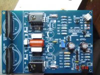
Why? The boards that I have, seem to be ungrounded. When you look at the output section of the silk-screen layer between the output transistors and the driver transistors you can plainly see the connections marked from left to right as follows; +40, SP, GND -40, but there is no connection for the speaker (-) lead. (see the picture attached below)
My question ? Should I connect both the ground lead from a central point on the power supply and the speaker (-) lead to the output of my amplifier board (marked GND). OR; Should I connect the amplifiers output (marked GND) to the central ground point and then connect the speaker (-) lead (via a different route) to the central grounding point? OR; Something entirely different?
I am confused!
Why? The boards that I have, seem to be ungrounded. When you look at the output section of the silk-screen layer between the output transistors and the driver transistors you can plainly see the connections marked from left to right as follows; +40, SP, GND -40, but there is no connection for the speaker (-) lead. (see the picture attached below)
My question ? Should I connect both the ground lead from a central point on the power supply and the speaker (-) lead to the output of my amplifier board (marked GND). OR; Should I connect the amplifiers output (marked GND) to the central ground point and then connect the speaker (-) lead (via a different route) to the central grounding point? OR; Something entirely different?
Attachments
...OR; Should I connect the amplifiers output (marked GND) to the central ground point and then connect the speaker (-) lead (via a different route) to the central grounding point?
This what I did. And don't forget the input signal ground (SG). It should also go to the central ground, because on most boards that I know of, there is not board connection between these two grounds.
Generally it is better to create a Main Audio Ground (MAG).
All CIRCUITS go to that MAG.
The Power +ve and -ve leads AND the Zero Volts lead go as a twisted triplet to the MAG.
The speaker leads go as a twisted pair to the MAG.
The Amplifier power input leads,+ve, -ve & Power Ground go to the MAG.
The Signal generally has it's own circuit that goes from input socket to amplifier input.
Most amplifier PCBs have an internal reference connection between Power Ground and Signal Ground. If not, then a reference, single wire, connection must go from Signal ground to MAG.
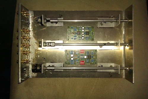
My first build
Hi All, just finished my first ever major electronics project.
2 H140 Monoblock power amps.
ESP pre amp with phono stage
Pre Amp PSU.
Amazing fun (and frustration) and sounds great (even f I do say so myself)
I decided from the outset to go total Naim Clone as you can see from the photo, and to use the best components I could afford, the biggest PITA was the casework, the power amps are engineered (i.e angle and countersunk screws holding everything together and the smaller cases are welded with lumiweld low temp aluminium weld which is amazing stuff for this type of project.
Even the wife likes the sound!!
086 by robertsearby, on Flickr

080 by robertsearby, on Flickr

081 by robertsearby, on Flickr

093 by robertsearby, on Flickr

201 by robertsearby, on Flickr
Hi All, just finished my first ever major electronics project.
2 H140 Monoblock power amps.
ESP pre amp with phono stage
Pre Amp PSU.
Amazing fun (and frustration) and sounds great (even f I do say so myself)
I decided from the outset to go total Naim Clone as you can see from the photo, and to use the best components I could afford, the biggest PITA was the casework, the power amps are engineered (i.e angle and countersunk screws holding everything together and the smaller cases are welded with lumiweld low temp aluminium weld which is amazing stuff for this type of project.
Even the wife likes the sound!!
086 by robertsearby, on Flickr
080 by robertsearby, on Flickr
081 by robertsearby, on Flickr
093 by robertsearby, on Flickr
201 by robertsearby, on Flickr
Last edited:
Well spotted, Revolver it is,( chuffed £30 off Flea Bay) without arm.
Mission 774LC and Ortofon red, had a mare with the belt though couldn't find one anywhere, ended up chopping a couple of centimeters out of the old one and supergluing it back together. Not ideal but blown if I can hear the join.
Mission 774LC and Ortofon red, had a mare with the belt though couldn't find one anywhere, ended up chopping a couple of centimeters out of the old one and supergluing it back together. Not ideal but blown if I can hear the join.
Very convincing case work there . You really did the total "Chrome Bumper" clone thing and very nicely. 🙂
You may have to increase the heatsink size if you want to use medium to full power. That little 'sink might suit a 25W amplifier sealed inside a case but unless I'm mistaken by appearance, it will get quite hot with almost no airflow when pumping bass, if not thermally coupled to the outer case as the originals were.
You may have to increase the heatsink size if you want to use medium to full power. That little 'sink might suit a 25W amplifier sealed inside a case but unless I'm mistaken by appearance, it will get quite hot with almost no airflow when pumping bass, if not thermally coupled to the outer case as the originals were.
Hmm.... 'just realized the thin piece of metal coupling the transistors to the heatsink is not quite up to it either. The transistor rear face should be fully in contact with the heatsink washer + sink or any thick (>3mm) "L" bracket attached to the flat face, so that needs to be substantial and so does the coupling.
Suggestion - continue the clone principle and drop the heatsink - use a scrap of heavy wall RHS or solid aluminium extrusion as long as the PCB width and at least 30 mm wide x a suitable thickness to mount the transitors properly with the PCB still at a convenient height. Bolt it flat to the bottom of the case with heatsink compound applied between. It doesn't have to be the insulating type compound in that position so the powdered metal sort used to mount CPU coolers in your PC is also OK. You can even fit right-through mounting bolts from below to attach the Transistors.
Suggestion - continue the clone principle and drop the heatsink - use a scrap of heavy wall RHS or solid aluminium extrusion as long as the PCB width and at least 30 mm wide x a suitable thickness to mount the transitors properly with the PCB still at a convenient height. Bolt it flat to the bottom of the case with heatsink compound applied between. It doesn't have to be the insulating type compound in that position so the powdered metal sort used to mount CPU coolers in your PC is also OK. You can even fit right-through mounting bolts from below to attach the Transistors.
Yes, Ian has got it right. I just wrote a whole similar message just to find he had beat me to it. I would also raise those power cables away from the hot heatsink.
I have built (and blown up) many of these clone boards and I think it is a good idea to mount the transistor in the bias control on the heat sink to form a vbe multiplier to reduce the risk of thermal runaway.
Also, the version which you have used removes the safety circuit which was in the original Naim design so you might want to think of some speaker protection modules (plenty on flea bay). You will need a separate AC supply for this of 12-15v.
Nice metalwork.
microx
Also, the version which you have used removes the safety circuit which was in the original Naim design so you might want to think of some speaker protection modules (plenty on flea bay). You will need a separate AC supply for this of 12-15v.
Nice metalwork.
microx
Just prepare to finish 🙄
An externally hosted image should be here but it was not working when we last tested it.
An externally hosted image should be here but it was not working when we last tested it.
An externally hosted image should be here but it was not working when we last tested it.
I'd agree that some form of protection is necessary, particularly if we mess with speakers when the power's on. I guess we see many original Naim amplifiers with the parts of the protection circuits pulled, so it must be tempting to assume that's OK and leave it like that. Many amps once had no protection either and so, died when shorted whilst there was output, even with fuses. Times were different though and amplifiers weren't messed with, had capacitors giving DC protection for the speakers and the system likely remained undisturbed for years.......I think it is a good idea to mount the transistor in the bias control on the heat sink to form a vbe multiplier to reduce the risk of thermal runaway......
Also, the version which you have used removes the safety circuit which was in the original Naim design so you might want to think of some speaker protection modules (plenty on flea bay). You will need a separate AC supply for this of 12-15v....Nice metalwork. microx
Bias control is not simple since this is not an emitter follower output stage (EF) where you certainly should use the output stage transitors as the temperature refererence for bias control. With a Complementary Feedback Pair (CFP) design as used on the P3a for example, the appropriate temperature reference point is actually the driver transistors. When the design is Quasi-Complementary, as is this Naim, we have a hybrid of both topologies but the heat sense point can never be correct because the points of reference change as the output switches from the positive output polarity to the negative. Bias passes through both output transistors in series so bias is always going to wrong for both, to some degree.
It's tolerable in real amplifiers or we wouldn't be cloning them but if you attach the bias control transistor (Vbe multiplier) to a Quasi output stage heatsink, it will undercompensate and thermal runaway eventually occurs - see also #1174, but excuse the other dialogue there). Commercial "Quasi" amplifiers all seem to use a small transitor mounted near the output stage, rather than on any heatsink. I have seen thermistor controlled and strange combinations of various sensor devices but this isolated transitor which is incredibly slow to reach best operating point on warm-up, has proven reliable after a bit of development work on the specific designs.
I would just accept that we are stuck with it, follow the original layout as closely as practical with our clone boards and just move on.
Ian, you make a correct and valid point when you say that quasi-comp circuits are hard to compensate because what is right for one half will at the same moment be wrong for the other but as often happens practice does not allways follow the theory. When I was playing with these boards a while back I found that I could set the bias and it would remain steady after 15-20 mins but then if the amp was driven at a moderate level the bias would soar upwards. The kits I had came with "sanken" o/p transistors which I am sure were fakes. When I changed them for 2SC5200 also for sure fakes BUT much better ones the problems were less and when I moved the bias circuit to the heatsink the bias was much more stable. It's one of those things that worked for me???.
Those who remove the safety circuit swear it lowers distortion and I maybe it does but only when the safety circuit begins to conduct which is, in a non fault condition, where the amp would start to distort anyway pushed hard enough to generate enough DC offset, As you say it's probably best left alone but are we not here to experiment.
microx
- Home
- Amplifiers
- Solid State
- NAP-140 Clone Amp Kit on eBay