Hi Gaborbela, thanks for the answer. I read about the differential HFE. I have two issues though 1) I'm not sure how to measure hfe with a dmm. 2) I hate to mess around with the board, desoldering transistors since it actually works and sounds very nice. Is there anything else that can be done? (adding cap at the output?). Is 63-69mv abnormal and too much for the speaker drivers?
Hi Gaborbela, thanks for the answer. I read about the differential HFE. I have two issues though 1) I'm not sure how to measure hfe with a dmm. 2) I hate to mess around with the board, desoldering transistors since it actually works and sounds very nice. Is there anything else that can be done? (adding cap at the output?). Is 63-69mv abnormal and too much for the speaker drivers?
Hi,
IMO, 65mV is not that much. If you like values closer to 0mV, the input transistors have to be hfe matched.
Avondale recommends T1 hfe to be 10% bigger than T2, which is beneficial for the balance with audio signals (less distortion), but will spoil a little bit the 0mV output. May be that's what happened when you replaced the transistors. I guess the first pair was better matched, even though unintentionally.
Also the input resistors combination must be equal (or very close) to the 27k that's in the feedback path. You can tweak the values slightly for better results. For example instead of 24k+2.7k you could use 24k+3k. It's easier to replace a resistor than a transistor.
Regards.
Thanks Ruwe, you always get to the point. That's exactly what I was looking for. Replacing a resistor worries me less than a three-lead transistor! When I feel courageous enough, will try the supplied BC550, to see if they're better matched
I'm not sure how to measure hfe with a dmm.
Hello
That is the problem !😉
You must match those two transistors as close as possible . Matching the LTP can improve the sound also (a little bit)
Do not use capacitors on the output !!
Actually if you like the sound you can leave it how is it . That offset is acceptable .
Just check the offset after the amplifier warm up . If the offset increase that would be a bigger problem .
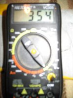
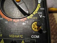
On your DMM here is some small holes and marked PNP & NPN that is for measure the transistors hFE .
Some transistor PNP & some NPN , U have to use those holes which category the transistor belong . You can find the transistor info on the net .
For exam. BC546B Data , and you can get the information if is PNP or NPN .
Please do not be afraid , you can not damage the transistor while U measure the hFE .
I dont know what type of DMM you have .
Most DMM has access to measure transistor hFE .
Greets
Hi Gaborbela, thanks for the answer. I read about the differential HFE. I have two issues though 1) I'm not sure how to measure hfe with a dmm. 2) I hate to mess around with the board, desoldering transistors since it actually works and sounds very nice. Is there anything else that can be done? (adding cap at the output?). Is 63-69mv abnormal and too much for the speaker drivers?
Hello
That is the problem !😉
You must match those two transistors as close as possible . Matching the LTP can improve the sound also (a little bit)
Do not use capacitors on the output !!
Actually if you like the sound you can leave it how is it . That offset is acceptable .
Just check the offset after the amplifier warm up . If the offset increase that would be a bigger problem .
On your DMM here is some small holes and marked PNP & NPN that is for measure the transistors hFE .
Some transistor PNP & some NPN , U have to use those holes which category the transistor belong . You can find the transistor info on the net .
For exam. BC546B Data , and you can get the information if is PNP or NPN .
Please do not be afraid , you can not damage the transistor while U measure the hFE .
I dont know what type of DMM you have .
Most DMM has access to measure transistor hFE .
Greets
Attachments
Nice NAP140
Hi,
I notice that the Q5 did not attach to heat sink. In summer, at loud volume, the power transistor could heat up very quick and destroy itself. It is called thermal-run-away.
Just my observation.
Lou
Hi,
I notice that the Q5 did not attach to heat sink. In summer, at loud volume, the power transistor could heat up very quick and destroy itself. It is called thermal-run-away.
Just my observation.
Lou
photos of my amplifier just completed:
ignatius little projects
Hi,
I notice that the Q5 did not attach to heat sink. In summer, at loud volume, the power transistor could heat up very quick and destroy itself. It is called thermal-run-away.
Just my observation.
Lou
I've tested it for hours at high volumes (high enough to go deaf) with DJ sessions without heating problems in q5. I appreciate the advise, this summer I will observe how it behaves.
Thanks
Good looking amp. Nice implementation of potentiometer and input selector at the rear.
How does it sound?
How does it sound?
photos of my amplifier just completed:
ignatius little projects
Last edited:
Q5
Hi,
Sorry, I was not making it clear.
Q5 is responsible to bias 2sc5200 and TIP transistor and if heat sink temperature rise, Q5 will sense the heat, and Q5 Vce will drop and reduce the current of these 4 transistors.
Q5 will ensure thermal stability of these 4 transistors.
Q5 itself wil never over heat.
Lou
I've tested it for hours at high volumes (high enough to go deaf) with DJ sessions without heating problems in q5. I appreciate the advise, this summer I will observe how it behaves.
Thanks
Good looking amp. Nice implementation of potentiometer and input selector at the rear.
How does it sound?
It sounds very well, very correct amplifier.
Gigaworks kit
Does anyone have a copy of the Bill of Materials and/or Schematic for the Gigaworks board? I received the kit a few days ago, but with no documentation. I've tried contacting the seller with no responses, though I'm sure there may be a language barrier, so I can understand.
The silkscreening on the boards are driving me crazy. They will refer to the value of the part in some locations, and then other locations refer to the part's reference name, like q4, without a clue which type of transistor actually goes there.
Attached is a rough BOM I've put together from the contents of the kit.
Attachments
gigawork documents
I have post in my blog the documents and schematic gigawork sent to me, in HD:
ignatius little projects: Diy Naim Nap-140 amplifier
Does anyone have a copy of the Bill of Materials and/or Schematic for the Gigaworks board? I received the kit a few days ago, but with no documentation. I've tried contacting the seller with no responses, though I'm sure there may be a language barrier, so I can understand.
The silkscreening on the boards are driving me crazy. They will refer to the value of the part in some locations, and then other locations refer to the part's reference name, like q4, without a clue which type of transistor actually goes there.
Attached is a rough BOM I've put together from the contents of the kit.
I have post in my blog the documents and schematic gigawork sent to me, in HD:
ignatius little projects: Diy Naim Nap-140 amplifier
Bill of materials
Salesmonster,
the components in your bom file match the parts I received in my kit, (B11551B pcb from hifidiy.net). Also the guy sent me the same schematic as posted by juluska on his blog.
Like you I also received 100uf/16v instead of 47uf/50v.
The 39p and 1K8 are not shown in the schematic, I wonder if they are optional.
Here is the bill of materials.
Jan
Salesmonster,
the components in your bom file match the parts I received in my kit, (B11551B pcb from hifidiy.net). Also the guy sent me the same schematic as posted by juluska on his blog.
Like you I also received 100uf/16v instead of 47uf/50v.
The 39p and 1K8 are not shown in the schematic, I wonder if they are optional.
Here is the bill of materials.
An externally hosted image should be here but it was not working when we last tested it.
Jan
juluska and 2Bak,
Thanks for the help...I can now get busy building. Also, have you had any issues with the orientation of Q5 as mentioned in posts #353/354? Should I follow the silk screen?
Thanks again!
SM
Thanks for the help...I can now get busy building. Also, have you had any issues with the orientation of Q5 as mentioned in posts #353/354? Should I follow the silk screen?
Thanks again!
SM
juluska and 2Bak,
Thanks for the help...I can now get busy building. Also, have you had any issues with the orientation of Q5 as mentioned in posts #353/354? Should I follow the silk screen?
Thanks again!
SM
the orientation is correct in the pcb. I didn't have any problem.
Whats fried
Hi Everybody,
i am a newbee and have decided for the NAP 140 as my first project. To stay as simple as possible i purchased a complete kit wit PSU similar to the often in this forum seen hifidiy.net kit. UK POWER AMP KITS W POWER SUPPLY REFER NAP140 NAP-140 - eBay (item 160365344031 end time Apr-24-10 11:03:20 PDT)
I put everything together, carefully i thought, mesured the Psu, connected to the ampboards and pu power on it. During the nextseconds i heard a little sizzle and felt the heatsink become warm and the MPC71 - Metal Plate Cement Resistors turned very hot and slight smoke emited from them. I checked my work and found out that i interchanged Q1/TIP42C with Q2/TIP41C. I removed them and soldered them back in the corret place. I powered the syste up again and verything stayed cool and nice and was able to adjust the Vr to 6mv. I added input signal and mesured about 2V of output and thought "fine"🙂! Connected one speaker and except some short rustle no noise 😱 but the -V control LED of the power supply dimed. Disconnecting the speaker the LED come up again.
So, i may have fried something.
I may have a aditional issue, PSU cabeling .....
Is there somebody out there who has a idea which components are likely to be fried (should be replaced) and which are less likely to be damaged and how to go on.
Here some pigs and dogs
https://docs.google.com/leaf?id=0ByRv1Th3OtLBMTRmOTM2ZTUtYTczYi00MDdhLTkyODctNWI3NzUxZDk3NGVj&hl=en
Sincerely Dispaired
Haggyhug
The output transistors need to be isolated from the main heatsink.
The first time probably you burned the output transistors and the TIP41/42 transistors....do you know how to test the transistors?
Also you really need some fuses after the PSU capacitors...probably your supply is working with short circuit....thats why the LSD is dimming.
My advice is to find someone who knows what to do...and fix your amplifier.
I notice C4 and C5 are also reversed. The English translated instructions are wrong comparing to the original Chinese ones as seen in post 513.
The .22ohm resistors will blow easily so would be worth checking as well. (I know from experience). Replacements for the output transistors can be MJL3281A which are better and actually cheaper , (as butch_vlad just said, make sure you use the insulating pads). Its also worth replacing Q5 with a TIP41C and mounting it directly to the output transistor with leads as it will provide better thermal protection.
The .22ohm resistors will blow easily so would be worth checking as well. (I know from experience). Replacements for the output transistors can be MJL3281A which are better and actually cheaper , (as butch_vlad just said, make sure you use the insulating pads). Its also worth replacing Q5 with a TIP41C and mounting it directly to the output transistor with leads as it will provide better thermal protection.
Thanks butch_vlad and repeet,
you cant see that on the pictures but the outputs are insulated with a transparent film pad that came with them. The C4 C5 position is incorrect in the assambly instruction compared to the circuit sheme and all the pictures i found on t he net, will reverse those.
If i have a shortcircuit and i assume its not a soldering issue because its identical on both boards, one of the circuit parts is producing the shortcircuit. Which fried circuitpart is likely to produce a shortcut? So, will have to desolder all transistors, diodes and the 0,22Ohm resitors, mesure them and order new improved parts. This howto may help me.Electronics Tips: Measurements: Testing Diodes and Transistors
Thanks so far and a nice weekend
haggyhug
Hi haggyhug,
IMO, both TIP41 and 42 are gone. You can't put them at 40V in reverse and then expect to work.
The smoke from the output emitter resistors, means that the output transistors were turned on very, very hard, but hopefully survived (lack of smoke later), but I wouldn't bet for it. One of them, on the negative line is suspicious. I guess this is the one that shorts your negative power supply rail. If that's the case, make sure that you still have good speakers.
It's not reliable to measure power transistors or even the drivers with multimeter diode check. I've had many occasions when they measure correct, but fail and go short, if you try to use them with higher currents as supposed. May be it's safer to replace the power transistors too.
Regards
- Home
- Amplifiers
- Solid State
- NAP-140 Clone Amp Kit on eBay