Maybe an IEC inlet boot, a bit of cutting and a hot air gun? Or maybe there's something similar on ebay?
Might need some practice with how PVC handles when attacked with a hot air gun 😱
Might need some practice with how PVC handles when attacked with a hot air gun 😱
I managed to stretch a standard IEC boot that fitted a normal rectangular housing to fit onto a square IEC.
Without resorting to heating it stretches, but immediately returns to size, elastic. But it did creep and eventually I could get it over the bigger can.
Without resorting to heating it stretches, but immediately returns to size, elastic. But it did creep and eventually I could get it over the bigger can.
That's sensible. PVC does break down with heat and the softer it is, the lower the temperature this begins to occur. PVC is unusual among plastics, being a variable blend of a fluid plasticiser and rigid polyvinyl chloride which, as the chloride bit might suggest, tends to form acid residues with moisture in the air when it's been smoked by excess heat. It literally gets up your nose in an excruciating way too......Might need some practice with how PVC handles when attacked with a hot air gun 😱
Care with the low heat setting and temperature checks should avoid any smoking plastic though.
I think I found a better power transformer option. From Antek, 200VA Dual primaries, and Dual Secondaries 28V x2 / 56V CT, 3.6A, with static & Magnetic shield. With two transformers I'll have the equivalent to what Ian ordered. I'll use a smaller separate transformer for the preamp supply. They are 32U$ each + 50$ shipping. I think that's the best option. Also they fit into my planned enclosure with a height of only 63mm (Case is 75mm inside).
DIY Audio Amp Toroidal Power Transformer 200VA 28V X2 56V Ct P N as 2228 | eBay
DIY Audio Amp Toroidal Power Transformer 200VA 28V X2 56V Ct P N as 2228 | eBay
To ease the schematic discussion, here the schematic with parts Ident. I kept the original NAP140 major part number...
When the Classic NAP250 amplifier appeared the output transistors were 10 MHz (BDY type) devices.
These are pedestrian by the standards of the Sanken devices and if the Sankens permit better linearity at high frequency this reduces the need to stretch the value of R17 to 1k to maximise open loop gain.
The downside of the stretch is limiting TR1 current to 0.5 mA which affects the slew rate capability.
A few posts back I mentioned having bought a Nait 5i which was superceded a short time later by the Nait 5i which according to the reviewer had a slightly reduced negative feedback factor - leaving that an unexplained mystery.
The NAP200 circuit has given a clue - I can see the LTP current has been increased which would improve the slew rate capability at the expense of some reduction in open loop gain due to TR1 collector load being reduced to 270R.
The rest of the changes I see as frequency tuning refinements to match.
Of these R18 the collector load for TR2 has been a point of continuing interest in previous posts.
The reduction of R18 from 22k to 5k6 is notable as that would increase the voltage seen by TR2 collector which in turn would have the effect of reducing the Miller capacitance from collector to base.
In the Classic circuit using slower output (BDY type) devices TR2 collector voltage due to the 22k value will be less and Miller capacitance greater.
If the BDY's are replaced by Sankens, the circuit still remains as a template geared for BDY parts. The NAP200 changes that situation for the better.
In the early Nait amplifiers with lower supply rails the value is 27k making TR2 collector voltage even lower to accomodate even slower output devices.
Does increasing the input LTP tail current and reducing the collector/drain load value result in a lower open loop gain?.................. - I can see the LTP current has been increased which would improve the slew rate capability at the expense of some reduction in open loop gain due to TR1 collector load being reduced to 270R. ............
I was considering maybe using a piece of flat heat-shrink tubing, but opened up a little and sealed above the transistors.
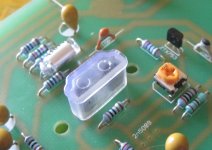
Had a brainwave last night and I've found that the protective cover from the end of an HDMI lead fits perfectly and is a snug interference fit, see the attached.
Chris
Attachments
Does increasing the input LTP tail current and reducing the collector/drain load value result in a lower open loop gain?
As you intimate, no. Re reduces in the same proportion as the collector load.
Also...
The ratio of Tr1 and Tr2 collector resistors remains approximately the same from new to old.
1K:22K
0.27K:5.6K
FWIW my amp runs 1.5K:22K
I liked that high current TR1+2. I have never been that brave. The 270/5K6 looks about right.
I really must learn simulations to know a little more. I have kept aways from it because I felt it would " corrupt " my thoughts.
I really must learn simulations to know a little more. I have kept aways from it because I felt it would " corrupt " my thoughts.
................
The NAP200 circuit has given a clue - I can see the LTP current has been increased which would improve the slew rate capability at the expense of some reduction in open loop gain due to TR1 collector load being reduced to 270R. .................
Does increasing the input LTP tail current and reducing the collector/drain load value result in a lower open loop gain?
I think that increasing the tail current actually increases the OLG.As you intimate, no. Re reduces in the same proportion as the collector load............
One has to use an increase in the input LTP Re values to bring the OLG back down to where it was at the lower tail current.
I wonder what Mjona meant to say?
D.Self and R.Cordell have discussed this. Cordell in more detail.I liked that high current TR1+2. I have never been that brave. The 270/5K6 looks about right.
I really must learn simulations to know a little more. I have kept aways from it because I felt it would " corrupt " my thoughts.
Very high tail currents can bring big benefits but that often means introducing cascode to keep dissipation down.
Very high hFE also becomes helpful, or adopting jFETs, to limit the input offset current that would otherwise be excessive.
I think that increasing the tail current actually increases the OLG.
As I understand it...
Let's say we double the LTP current, then Re halves.
Then we have to half the collector load (otherwise we lose LTP balance)
Result: OLG stays about the same.
If there is no (external) Re to halve?
And yes, it follows that the LTP should still remain in balance by adjusting the collector/drain load. Except with the unbalanced Naim topology.
And yes, it follows that the LTP should still remain in balance by adjusting the collector/drain load. Except with the unbalanced Naim topology.
Sorry I used the wrong terminology (again 🙁). I meant re' not Re.
I meant the intrinsic emitter resistance which is ~25/Ic Ohms (where Ic is in mA)
My comments were for the Naim circuit with no external emitter resistors.
I meant the intrinsic emitter resistance which is ~25/Ic Ohms (where Ic is in mA)
My comments were for the Naim circuit with no external emitter resistors.
And yes, it follows that the LTP should still remain in balance by adjusting the collector/drain load. Except with the unbalanced Naim topology.
The VAS transistor B-E "regulates" the TR1 collector resistor voltage. As I've said before the LTP currents are well matched in the Naim circuit.
Mjona what do you think is the TR1 TR2 bias current in the NAP200 circuit, and do you think the NAP140 difference of about 10% HFE mismatch in TR1 & TR2 (TR1 being higher) to give the 'Naim sound' still apply here?
howarthcd excellent discovery for the HDMI cover. I went a slightly more extensive way 😉 Pictures to follow...
Thanks
SB
howarthcd excellent discovery for the HDMI cover. I went a slightly more extensive way 😉 Pictures to follow...
Thanks
SB
Last edited:
matching current alone is not the target for a balanced Input LTP.The VAS transistor B-E "regulates" the TR1 collector resistor voltage. As I've said before the LTP currents are well matched in the Naim circuit.
In order to avoid another ride on the merry-go-round of pedantry. I will rephrase #1892 as:
As I understand it...
Let's say we double the LTP current, then Re halves.
Then we have to half the collector load (otherwise we lose LTP current balance)
Result: OLG stays about the same.
As I understand it...
Let's say we double the LTP current, then Re halves.
Then we have to half the collector load (otherwise we lose LTP current balance)
Result: OLG stays about the same.
Thanks, I got that conclusion from your previous posts.In order to avoid another ride on the merry-go-round of pedantry. I will rephrase #1892 as:
As I understand it...
Let's say we double the LTP current, then Re halves.
Then we have to half the collector load (otherwise we lose LTP current balance)
Result: OLG stays about the same.
So that prompts the question:
What does the introducing of the external Re to degenerate the Input LTP do?
We know that degenerating the LTP reduces the OLG.
The thing to watch is re will degrade the Naim effect. One could always do a ratio on that to restore the balance. For example 25 R 39R. I plucked them from the air so not calcualted.
I think the arguement is this. If wanting to keep loop gain the same for stability reasons if Re + re = original internal resistance all is well. What you get as a bonus is more drive current into the VAS. It is then a no mans land as it is supposed to be pure current drive. Most at this poin prefer to speak slew rates of charging and discharging the Cdom of the VAS. The loop gain is also the internal resistance of the VAS into the collector load ( collector of TR6 if Avondale and collector of TR 4 ). That will be massive.
I think the arguement is this. If wanting to keep loop gain the same for stability reasons if Re + re = original internal resistance all is well. What you get as a bonus is more drive current into the VAS. It is then a no mans land as it is supposed to be pure current drive. Most at this poin prefer to speak slew rates of charging and discharging the Cdom of the VAS. The loop gain is also the internal resistance of the VAS into the collector load ( collector of TR6 if Avondale and collector of TR 4 ). That will be massive.
- Home
- Amplifiers
- Solid State
- NAP-140 Clone Amp Kit on eBay